12V vs 24V Solenoid Coil: Which Voltage Should Pneumatic OEMs Standardize?
12V vs 24V solenoid coil selection becomes difficult when an OEM treats voltage as a simple catalog option instead of a machine-platform decision. I often see teams choose a coil that fits the valve tube, then discover cable loss, PLC loading, heat, or spare-part confusion after production begins. I recommend starting with the electrical architecture, then validating the coil under real operating conditions.
A pneumatic OEM should normally standardize on 24V DC solenoid coils for factory valve islands, PLC-controlled cabinets, and long cable runs. I recommend retaining 12V DC coils for battery-native machines where a voltage converter would add unnecessary complexity. In either case, the coil must pull in, hold, release, and remain within thermal limits at the lowest real terminal voltage in its hot operating state.
I approach voltage selection as a chain of engineering decisions: machine power architecture, coil current, cable voltage drop, magnetic force, duty cycle, heat, and spare-part control. A nameplate marked “12V” or “24V” is only the starting point. The real question is whether the complete pneumatic system remains reliable at the worst expected operating condition.
Why Do Pneumatic OEMs Keep Asking About 12V vs 24V Solenoid Coil Platforms?
I see this question arise because pneumatic OEMs often operate across several electrical environments. One machine may use a 12V battery, while another uses a 24V PLC cabinet and a dense valve island. If the voltage decision is not frozen early, teams can create avoidable wiring, maintenance, and supplier-control problems.
The right 12V vs 24V solenoid coil choice starts with the machine’s available electrical system, not with the coil catalog. I recommend that OEMs use 24V DC where the controls, sensors, and valve manifolds already run on 24V DC. I recommend 12V DC where the machine is fundamentally battery-native and conversion would add more risk than value.
Replacement Coils Require More Than a Voltage Check
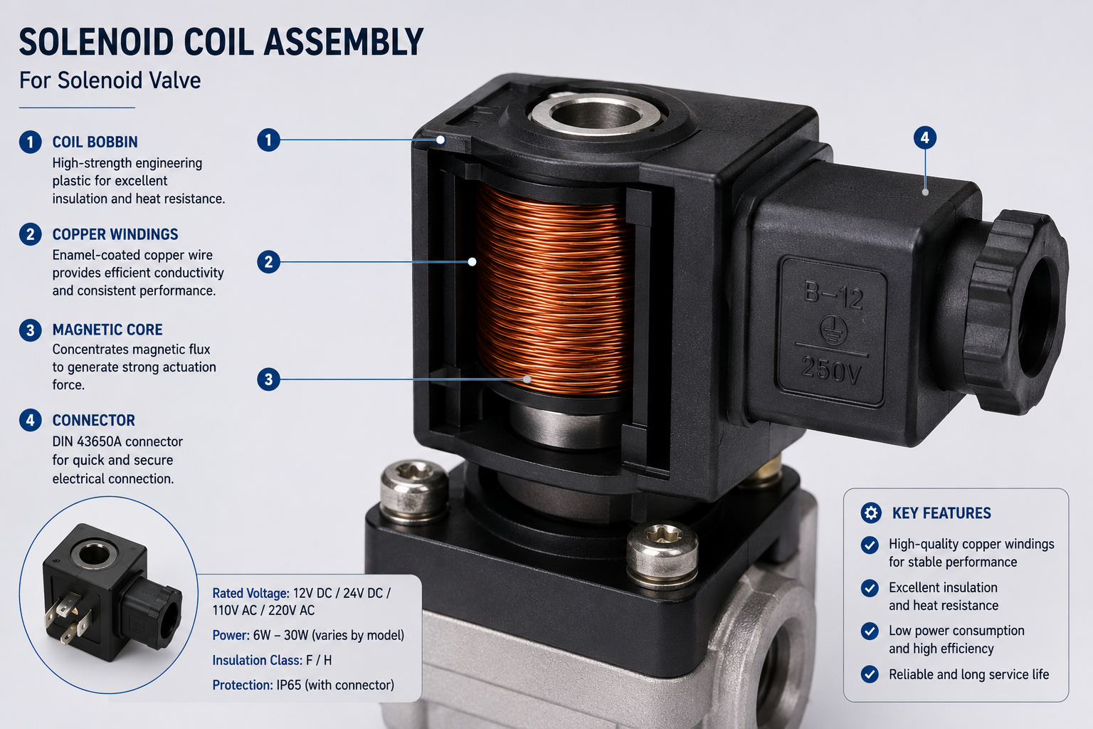
When I review a replacement-coil or second-source project, I do not assume that two coils are interchangeable because they share a diameter, height, or voltage marking. A replacement evaluation should confirm:
- Rated voltage: 12V DC, 24V DC, AC, or another nominal value
- Actual terminal voltage: measured at the installed coil, not only at the power supply
- Coil power and current: especially at normal operating temperature
- Connector type and pinout: DIN connector, plug-in connection, flying lead, or custom interface
- Duty cycle: 100% energized duty or intermittent cycling
- Valve geometry: armature tube, plunger, air gap, spring load, and pressure requirements
- Environmental conditions: cabinet temperature, manifold density, moisture, vibration, and contamination
A 24V DC coil may physically slide onto the same valve tube as a 12V DC coil. That does not make it electromagnetically equivalent. The winding resistance, wire diameter, number of turns, current, and thermal behavior may all differ.
New Platforms Should Begin With Control Power
For a new pneumatic OEM platform, I recommend defining the control-power architecture before specifying coil voltage. Factory automation commonly uses 24V DC because PLCs, I/O cards, sensors, relay interfaces, safety devices, and valve islands already operate at that level.1
Adding a separate 12V branch for pneumatic coils can introduce:
- An additional power supply or DC-DC converter
- More wiring and more terminals
- A second spare-part family
- More opportunities for incorrect installation
- More incoming-inspection and traceability requirements
I have seen projects where a seemingly minor voltage variation created a larger maintenance burden than the original component cost justified. In my view, platform consistency often matters more than small, isolated component differences.
What Is the Real Electrical Difference in a 12V vs 24V Solenoid Coil?
Many buyers know that 24V is twice 12V, but that fact alone does not explain the procurement and reliability impact. The important issue is how voltage changes current, cable losses, connector heating, output-card loading, and magnetic performance at the valve.
For the same nominal coil power, a 12V DC coil generally draws about twice the current of a 24V DC coil.2 I use this relationship to assess wiring and control-system loading, because higher current raises I²R losses in cables and contacts.3 However, the correct design still depends on the winding, valve load, duty cycle, and actual voltage at the coil terminals.
Current, Resistance, and Power
For a conventional DC solenoid coil, I use these basic relationships:
P = V × I
I = V ÷ R
P = V² ÷ R
Where:
- P is electrical power in watts
- V is voltage in volts
- I is current in amperes
- R is coil resistance in ohms
If two coil designs deliver similar nominal power, the lower-voltage design requires more current. For example, a 2.4W coil would draw approximately:
| Coil Voltage | Nominal Power | Approximate Current |
|---|---|---|
| 12V DC | 2.4W | 0.20A |
| 24V DC | 2.4W | 0.10A |
This simple example does not define a universal coil resistance. Coil resistance changes with winding design and rises as copper heats. Still, the current relationship helps me identify potential system issues early.
Higher current can mean:
- Greater cable voltage drop
- More connector contact heating
- Higher load on PLC transistor outputs
- Larger conductor requirements
- Less margin on shared power rails
Why Voltage Mismatch Is Dangerous
I advise OEMs to treat wrong-voltage installation as a preventable reliability risk, not as a field adjustment.
A 12V coil on a 24V supply is not “slightly stronger.” Since power rises with the square of voltage for a fixed resistance, the coil can consume far more power than designed.4 The winding may overheat quickly, insulation can degrade, and the valve assembly can become unsafe or unreliable.
A 24V coil on a 12V supply is not a safe low-power mode either. The coil may fail to pull in, may drop out under pressure, or may behave inconsistently after heating. Reduced voltage lowers current and ampere-turns, which reduces available magnetic force.5
Terminal Voltage Matters More Than the Supply Label
I recommend measuring voltage directly at the coil terminals during operation. A panel may have a 24V power supply, but the farthest valve can receive only 20V or 21V after cable losses, output-card drop, connector resistance, and shared-load sag.
A common 24V DC planning range is ±10%6, or approximately:
- Minimum: 21.6V
- Nominal: 24.0V
- Maximum: 26.4V
That range is useful for planning, but it does not replace validation. The coil must still work at the actual lowest expected terminal voltage, with the winding hot and the valve under its real mechanical and pneumatic load.
24VAC Is Not the Same as 24VDC
I also recommend separating 24VAC vs 24VDC solenoid requirements at the beginning of a project. The same number on a label does not mean that the coil design is interchangeable.
AC and DC coils use different electrical and magnetic design approaches.7 A 24VAC coil should not be substituted for a 24VDC coil without qualified engineering review and validation. For a deeper comparison, I recommend reading AC vs DC Solenoid Coils.
How Do 12V vs 24V Solenoid Coil Designs Affect Heat, Wiring, PLC Load, and Spares?
A voltage choice can look harmless on a schematic but become expensive on a production line. Higher current affects wire sizing and outputs, while poor standardization affects inventory and service accuracy. I recommend evaluating the coil as part of the complete valve, wiring, and maintenance system.
A 24V DC solenoid coil usually fits industrial pneumatic systems more easily because its lower current reduces cable and connector losses for comparable power. A 12V DC solenoid coil can still be the correct choice for battery equipment. I do not treat either voltage as inherently cooler, cheaper, or more reliable without reviewing power, duty cycle, ambient temperature, and valve conditions.

| Parameter | 12V DC Coil | 24V DC Coil |
|---|---|---|
| Typical power architecture | Battery equipment, mobile systems, short harnesses | PLC cabinets, factory automation, valve islands |
| Current at the same wattage | About 2× higher | About half of comparable 12V current |
| Voltage-drop sensitivity | Higher | Lower |
| Connector and harness heating | Higher I²R risk | Lower I²R risk |
| PLC output loading | More current per coil | Often easier to support more valves |
| Dense manifold suitability | Requires careful current budgeting | Often favorable for industrial platforms |
| Spare-part reality | Common in mobile OEM equipment | Common in industrial pneumatics |
| Wrong-voltage risk | 12V coil on 24V can overheat | 24V coil on 12V may not shift reliably |
Heat Depends on the Full Thermal System
I avoid statements such as “24V coils are always cooler.” Coil temperature is not controlled by voltage alone.8 I review the following conditions together:
- Coil power consumption
- Energized duty cycle
- Ambient temperature
- Valve-body temperature
- Manifold density
- Airflow around the valve island
- Actual terminal voltage
- Connector and contact quality
- Encapsulation and insulation system
For pneumatic valves, low-wattage coils may operate around 0.5W to 1.5W, while standard pneumatic coils often fall around 2W to 4.8W. The suitable value depends on the armature geometry, required force, response expectations, and heat limits. I would not apply high-power hydraulic-coil figures to compact pneumatic applications.
A manifold with 16 energized coils inside a 40°C cabinet creates a different thermal condition than one isolated valve in open air.9 I recommend reviewing adjacent-coil heating and cabinet airflow before freezing a continuous-duty specification. For a dedicated duty-cycle review, see Continuous Duty vs Intermittent Duty Solenoids.
Magnetic Force Is Not Defined by Voltage Alone
A coil must generate enough magnetic force to move and hold the armature under real conditions.10 That force depends on:
- Ampere-turns
- Core and plunger geometry
- Air gap
- Spring force
- Valve pressure load
- Friction and contamination
- Hot-state current
This is why a 12V coil and a 24V coil are not interchangeable electromagnetic designs merely because both fit the same tube. The supplier must engineer the winding around the armature tube and application requirements.
Spare-Part Control Is a Reliability Issue
I recommend that procurement teams evaluate spare-part strategy alongside electrical performance. Mixed-voltage inventories increase the likelihood of a maintenance error.11 Clear part numbering, durable voltage marking, connector keying, color coding, and incoming inspection all reduce that risk.
At SolenElec, I would typically recommend that OEMs verify coil identity through controlled specifications, resistance checks at a defined temperature such as R20, dimensional inspection, marking review, and functional testing. Buyers should also verify any claimed compliance documents and confirm that the applicable standard matches their intended market and product configuration.
Can Pneumatic OEMs Mix 12V and 24V Solenoid Coils on One Machine?
Mixed-voltage platforms can appear during machine upgrades, regional adaptations, or legacy-product transitions. The problem is that a mixed system may work on paper but create a field-service hazard. I recommend avoiding mixed 12V and 24V coil populations unless the machine architecture genuinely requires them.
I do not recommend mixing 12V and 24V coils on the same pneumatic platform unless both voltages are necessary and physically impossible to confuse. A 12V coil connected to 24V can overheat, while a 24V coil connected to 12V may not actuate the valve.12 Separate SKUs, keyed connections, labels, and error-proofing should be mandatory when mixed voltages remain unavoidable.

What Commonly Goes Wrong
I have seen maintenance teams focus on the mechanical fit of a replacement coil because that is the most visible criterion. The hidden risk is electrical compatibility. A mixed-voltage platform can lead to:
- Incorrect coil installation during field repair
- Burned 12V coils connected to a 24V rail
- Weak or non-shifting 24V coils connected to 12V
- Doubled inventory and purchasing complexity
- Harder IQC procedures
- Inconsistent service documentation
- Higher warranty and after-sales exposure
For more detail on overheating mechanisms, I recommend Why Does a Solenoid Coil Burn Out?.
When 12V Still Makes Sense
I would retain 12V DC when the machine is genuinely built around a 12V battery system. Typical reasons include:
- The battery is 12V nominal
- The wire harness is short and controlled
- Actuators, lamps, sensors, and auxiliary devices already use 12V
- A 24V conversion requires a DC-DC converter
- The converter would add failure points, EMI/EMC work, cost, or service complexity
The correct choice is not “upgrade everything to 24V.” The correct choice is to select the voltage that reduces total system risk.
When 24V Should Become the Platform Rule
I recommend a 24V DC platform rule when the OEM uses:
- PLC and remote I/O systems
- 24V DC control power
- Dense pneumatic valve islands
- Long cable runs
- Distributed pneumatic stations
- Continuous-duty or high-duty valve functions
- Centralized spare-part programs
A 24V platform can simplify documentation, power budgeting, wiring, and maintenance. It also aligns naturally with common industrial control architectures.
Same Bobbin, Different Winding
A voltage change does not always require new tooling. If the bobbin, center hole, height, terminal arrangement, and outer geometry remain unchanged, a supplier can often develop 12V and 24V versions through winding changes rather than a new mold.
However, I would still require revalidation of:
- Winding resistance at the specified reference temperature
- Pull-in and hold performance
- Coil current
- Temperature rise
- Marking and label control
- Connector configuration
- Hot-state operation on the actual valve
How Should Pneumatic OEMs Decide on a 12V vs 24V Solenoid Coil Standard?
A reliable standardization decision needs more than a purchasing preference. I recommend that engineering, procurement, quality, and service teams freeze the voltage rule together. This prevents late changes that affect wiring, drawings, supplier qualification, and spare kits.
I recommend standardizing 24V DC for factory pneumatic valve islands and PLC cabinets, while keeping 12V DC for battery-native machines. Before an OEM freezes either platform, I would validate real terminal voltage, current, cable drop, hot-state pull-in, duty cycle, thermal limits, connector design, and maintenance error-proofing. Voltage is a system decision, not a catalog filter.

| Application Condition | Starting Direction | What Still Needs Verification |
|---|---|---|
| 24V DC PLC valve island | Standardize 24V DC | Terminal voltage, coil power, heat, duty, connector |
| Long cable or distributed pneumatics | Prefer 24V DC | Cable drop and farthest-valve pull-in |
| Dense manifold with continuous duty | Prefer low-wattage 24V DC if force allows | Adjacent-coil temperature and power-supply budget |
| 12V battery mobile equipment | Keep 12V DC | Battery discharge voltage, harness drop, heat |
| Mixed installed base | Do not silently mix voltages | Labels, keyed interfaces, separate SKUs |
| Existing 12V coil with new 24V panel | Redesign the winding | Hot-state force, current, marking |
| Same bobbin with a new voltage | Consider winding change first | R20, pull-in, temperature rise, labeling |
Step 1: Identify the Machine Power Architecture
I start with the available supply system:
- Is the machine battery-native at 12V?
- Does the control cabinet already provide regulated 24V DC?
- Is there a mixed-voltage legacy design?
- Does a DC-DC converter already exist?
- Which voltage serves the sensors, HMI, PLC, and other actuators?
This step prevents the team from selecting a coil voltage in isolation.
Step 2: Define the Voltage Window
I recommend documenting the nominal voltage and allowed operating range, such as 12V DC ±10% or 24V DC ±10%. The project specification should also define:
- Minimum pull-in voltage
- Maximum continuous voltage
- Maximum expected supply sag
- Start-up and shutdown behavior
- Any AC supply that could appear in the system
Step 3: Measure Real Terminal Voltage
I do not accept a power-supply label as proof of coil voltage. I measure the voltage at the farthest coil with relevant loads energized.
The test should consider:
- Full manifold activation
- Longest cable route
- Connector aging or contact resistance
- PLC-output voltage drop
- Hot connector conditions
- Low battery state for 12V equipment
Step 4: Calculate Current and Cable Drop
I use I = P ÷ V as the first current estimate, then review cable length, conductor size, branch loading, fuse ratings, connector ratings, and output-card capacity.
A lower-current 24V coil can provide more margin on long runs, but the design still needs actual measurement. A poorly sized 24V harness can still produce an unacceptable terminal voltage.
Step 5: Define Magnetic and Thermal Limits
The coil specification should state:
- Required pull-in performance at hot state
- Hold performance
- Release behavior
- 100% duty or intermittent duty
- Ambient temperature
- Valve-island density
- Maximum coil temperature or permitted temperature rise
- Insulation and encapsulation requirements
For environmental planning, I also recommend How Ambient Temperature Affects Solenoid Coil Selection.
Step 6: Freeze Spare-Part and Error-Proofing Rules
I prefer one voltage per platform whenever possible. If multiple voltages are unavoidable, I recommend:
- Clearly different part numbers
- Permanent voltage marking
- Separate packaging labels
- Connector keying where feasible
- Controlled service manuals
- IQC checks based on drawing, R20, dimensions, and marking—not voltage text alone
Step 7: Validate at Hot State
The final test should not be “the coil clicked on a room-temperature bench supply.” I recommend a validation condition that combines:
Lowest expected terminal voltage + hot coil + maximum valve load
The valve should still:
- Pull in reliably
- Hold reliably
- Release correctly
- Stay within the specified thermal limits
OEM Example: A PLC-Controlled Pneumatic Valve Island
Consider an OEM with a 24V DC PLC, an 8-to-16-valve pneumatic island, DIN connectors, cable distances of 8 to 12 meters, 100% energized duty, and a 40°C control cabinet.
The wrong approach is to select any 12V or 24V coil that slides onto the existing armature tube.
I would use this evaluation path instead:
24V DC control architecture
→ Lowest terminal voltage at the last valve
→ Current per coil and total island current
→ Existing valve geometry and required magnetic force
→ 100% duty and cabinet temperature
→ 24V winding design
→ DIN connector and marking requirements
→ Hot-state validation
This process helps the OEM distinguish a mechanically compatible coil from a qualified platform component. It also gives procurement teams a clearer supplier-evaluation checklist. A capable OEM/ODM supplier should support coil design review, prototype validation, controlled manufacturing, and traceable quality documentation. At SolenElec, I would encourage buyers to review relevant quality-system records, inspection methods, and compliance documents for the exact product configuration rather than relying on general claims.
For connector selection, I recommend reviewing Plug-in vs Flying Lead Solenoid Coils. For a broader valve-matching process, see Pneumatic Solenoid Coils: How Do You Select the Right Coil for Your Valve?.
Frequently Asked Questions
Is 24V DC better than 12V DC for pneumatic solenoid valves?
I recommend 24V DC for most factory pneumatic systems because PLCs, sensors, valve islands, and control cabinets commonly use 24V DC. Its lower current can also reduce cable losses. However, 12V DC remains appropriate for battery-native equipment with short, well-controlled harnesses.
Can I connect a 12V solenoid coil to 24V?
No. I do not recommend connecting a 12V coil to 24V. The higher voltage can increase power dramatically and may overheat the winding, damage insulation, or shorten coil life. The correct action is to use a properly designed 24V coil and validate it on the intended valve.
Will a 24V coil work on a 12V supply?
I would not assume that it will work reliably. A 24V coil supplied with 12V has reduced current and magnetic force. It may fail to pull in, drop out under load, or become unreliable when hot. Engineers should validate the actual valve load and terminal voltage.
How do I measure solenoid coil voltage drop?
I recommend measuring DC voltage directly across the coil terminals while the coil is energized and the system is under realistic load. Test the farthest valve, activate relevant manifold loads, and repeat measurements when connectors and coils are warm. The power-supply display alone is not enough.
Can the same solenoid coil bobbin support both 12V and 24V?
Often, yes. I can use the same bobbin geometry when the tube diameter, height, terminals, and external dimensions remain unchanged. The supplier may change the winding design instead of creating a new mold. Still, each voltage version needs separate current, force, heat, and marking validation.
Conclusion
I recommend that pneumatic OEMs standardize on 24V DC for factory valve islands, PLC cabinets, distributed pneumatic systems, and long cable runs. I recommend keeping 12V DC for machines that are genuinely battery-native. The best 12V vs 24V solenoid coil decision is not based on a simple voltage comparison. It depends on real terminal voltage, current, cable drop, valve load, duty cycle, heat, and service controls. If you are qualifying a new coil platform, first use the pneumatic solenoid coil manufacturer checklist, then work with SolenElec to review the valve geometry, winding requirements, connector design, and hot-state validation plan before production is frozen.
"IEC 60204-1 Wire Color Codes: 24V DC, 110V AC, Safety ...", https://industrialmonitordirect.com/blogs/knowledgebase/iec-60204-1-wire-color-codes-for-industrial-automation-panels?srsltid=AfmBOoqjGLFbFI61O8p0gWKMJ281K1wTf3T0x1nmVuid6j0uszLdOoiq. Industrial machinery and programmable-controller standards commonly specify or describe 24 V DC control circuits and interfaces, supporting the article’s use of 24 V DC as a typical factory-automation control architecture. Evidence role: general_support; source type: institution. Supports: A standards or institutional source should show that 24V DC is a conventional supply level for industrial control and automation equipment.. Scope note: Standards support the prevalence and compatibility context, but they do not prove that every PLC, sensor, valve island, or factory system uses 24 V DC. ↩
"Electric Power", http://hyperphysics.phy-astr.gsu.edu/hbase/electric/elepow.html. The DC power relation P = V × I implies that, for a fixed power level, current is inversely proportional to voltage; therefore, a 12 V load draws about twice the current of a 24 V load at the same wattage. Evidence role: mechanism; source type: education. Supports: A basic electrical-engineering source should support the relationship between power, voltage, and current in DC circuits.. ↩
"Electrical equipment", https://irc.wisc.edu/export.php?ID=537. Joule’s law states that resistive heating is proportional to I²R, so increasing current increases heat generation and voltage-loss effects in wiring and contact resistance. Evidence role: mechanism; source type: education. Supports: A source should explain Joule heating and the proportional relationship between current squared, resistance, and heat dissipation.. ↩
"voltage - Is power proportional to V or V^2?", https://electronics.stackexchange.com/questions/543610/is-power-proportional-to-v-or-v2. Combining Ohm’s law with the power equation gives P = V²/R, showing that voltage applied to a fixed resistance raises dissipated power with the square of voltage. Evidence role: mechanism; source type: education. Supports: A source should support the equation P = V²/R and its implication that overvoltage can greatly increase power dissipation in a resistive winding.. ↩
"Solenoid", https://en.wikipedia.org/wiki/Solenoid. Solenoid magnetic field strength is commonly modeled as dependent on ampere-turns, so lowering supply voltage in a resistive DC coil reduces current and can reduce the magnetic force available for actuation. Evidence role: mechanism; source type: education. Supports: A source should explain that solenoid magnetic field strength depends on current and number of turns, and that reduced current can reduce actuation force.. Scope note: This supports the general mechanism; the exact pull-in force depends on the actuator geometry, air gap, materials, spring load, and valve pressure. ↩
"18.4 - Voltage Test", https://www.gt-engineering.it/en/technical-standards/en-iec-standards/en-iec-60204-1-safety-of-machinery-electrical-equipment-of-machines/18-6-functional-test/. Industrial-control documentation and standards-based equipment specifications commonly treat 24 V DC as a nominal control voltage with defined allowable operating ranges, making a ±10% planning window a conventional design assumption. Evidence role: general_support; source type: institution. Supports: A standards-based or institutional source should support the use of nominal 24V DC control supplies and typical tolerance planning in industrial equipment.. Scope note: The exact allowable range is device- and standard-dependent, so this citation would support the planning convention rather than a universal tolerance for all coils. ↩
"Solenoid Coil - Choosing AC or DC", https://tameson.com/pages/choosing-an-ac-or-dc-coil-for-a-solenoid-valve. Technical descriptions of solenoid actuators distinguish AC coils, which are influenced by inductive impedance and often use shading methods to reduce chatter, from DC coils, whose steady current is primarily set by winding resistance. Evidence role: mechanism; source type: education. Supports: A source should explain the different operating principles and design considerations of AC and DC solenoid coils.. Scope note: This supports the general non-interchangeability rationale; a specific coil substitution still requires the manufacturer’s rating and validation data. ↩
"Solenoid Coil Resistance vs Temperature", https://www.electricsolenoidvalves.com/blog/solenoid-coil-resistance-vs-temperature/?srsltid=AfmBOop5T3Mtp1fXtsfuXdXBLoEShTOIxJZ1LktiD6l4tbSKU3eyyKB8. Thermal analyses of solenoid actuators model coil temperature as a function of electrical losses, duty cycle, ambient temperature, and heat-transfer paths, rather than nominal voltage alone. Evidence role: mechanism; source type: paper. Supports: A paper should support that coil temperature rise depends on heat generation, duty cycle, ambient conditions, and thermal dissipation paths.. Scope note: This supports the general thermal mechanism; it does not establish temperature limits for the particular pneumatic coils discussed in the article. ↩
"Thermal Management for Electrical Enclosures in High ...", https://thermaledge.com/thermal-management-for-electrical-enclosures-in-high-temperatures/. Studies of enclosed electrical equipment and compact actuator assemblies show that ambient temperature, airflow, and neighboring heat sources affect component temperature rise, supporting the need to evaluate dense valve manifolds differently from isolated open-air valves. Evidence role: mechanism; source type: paper. Supports: A source should support that enclosure temperature, airflow, heat-source density, and adjacent heat generation affect component operating temperature.. Scope note: The citation would support the thermal context, not the exact temperature reached by a 16-coil pneumatic manifold in a 40°C cabinet. ↩
"Chap4 - Princeton University", http://commons.princeton.edu/motorcycledesign/wp-content/uploads/sites/70/2018/07/solenoid.pdf. Solenoid-actuator models describe armature motion as occurring when electromagnetic force exceeds opposing forces such as spring load, friction, pressure-related load, and inertia, with force strongly influenced by current, geometry, and air gap. Evidence role: mechanism; source type: paper. Supports: A source should explain that solenoid force must exceed opposing mechanical and fluid forces and varies with air gap, geometry, current, and magnetic materials.. Scope note: This supports the general actuation mechanism; the required force for a specific pneumatic valve must be measured or calculated for that valve. ↩
"Human Factors in Aviation Maintenance: Understanding ...", https://commons.erau.edu/cgi/viewcontent.cgi?article=3465&context=publication. Human-factors guidance on maintenance error identifies part similarity, labeling limitations, and procedural complexity as contributors to wrong-part selection and installation errors. Evidence role: general_support; source type: government. Supports: A human-factors or maintenance-safety source should support that similar parts, inadequate labeling, and complex procedures can increase wrong-part or maintenance errors.. Scope note: This supports the general maintenance-risk mechanism; it does not quantify the specific error rate for mixed 12 V and 24 V solenoid-coil inventories. ↩
"What Causes Solenoid Valve Coils To Burn Out?", https://clarkcooper.com/CCblog/?p=99. Electrical power relations and solenoid-force principles together show that overvoltage can substantially increase winding heat, while undervoltage can reduce current and electromagnetic force below the pull-in requirement. Evidence role: mechanism; source type: education. Supports: A technical source should support that overvoltage increases coil power and heat, while undervoltage reduces current and magnetic force needed for pull-in.. Scope note: This supports the mechanism; actual overheating time or actuation failure depends on coil resistance, thermal design, duty cycle, and valve load. ↩