Continuous Duty vs Intermittent Duty Solenoids: How Engineers Choose the Right Solenoid Duty Cycle
A solenoid duty cycle can look correct on a datasheet and still fail under real machine conditions. Engineers often compare percentages but overlook maximum ON time, cooling time, and hot-state force. That gap can cause overheating or unreliable actuation. I recommend starting with the machine’s actual operating profile instead.
Engineers should select a solenoid duty cycle from the longest credible ON time, shortest OFF time, total cycle duration, switching frequency, thermal environment, voltage range, stroke, and required force. They should then validate temperature and magnetic performance in the actual assembly. A duty-cycle percentage alone is not a complete specification.

The central engineering principle is simple: duty cycle is not merely a percentage. It is a thermal, time, and force requirement. The following sections show how I move from an ON/OFF profile to a defensible coil specification and a representative validation plan.
What Does Solenoid Duty Cycle Actually Mean?
A solenoid duty cycle appears easy to calculate, but a percentage can hide critical operating details. If engineers treat the result as a complete rating, they may apply a coil for much longer than its permitted energization time. A useful specification must describe both the ratio and the timing.1
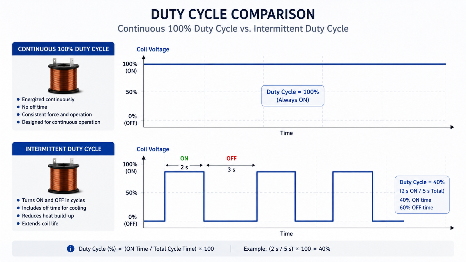
Solenoid duty cycle is the percentage of one operating cycle during which the coil remains energized.2 Engineers calculate it by dividing ON time by total cycle time. However, they must also specify maximum ON time, minimum OFF time, cycle duration, reference cycle, and switching frequency.

How do I calculate duty cycle?
I use this basic solenoid duty cycle calculation:
The calculation produces the energized percentage of a complete cycle.
| ON Time | OFF Time | Duty Cycle |
|---|---|---|
| 1 s | 9 s | 10% |
| 5 s | 15 s | 25% |
| 30 s | 30 s | 50% |
| Continuous | — | 100% |
The formula is necessary, but it is not sufficient.
Consider these two operating profiles:
- 1 second ON and 9 seconds OFF = 10%
- 60 seconds ON and 540 seconds OFF = 10%
Both profiles have the same mathematical percentage. However, they do not necessarily create the same coil temperature pattern.4
During a one-second pulse, the coil’s thermal mass may limit the immediate temperature rise. The following nine seconds provide frequent cooling opportunities. During a 60-second energization period, the coil generates heat continuously for much longer before cooling begins. The 540-second OFF period may eventually provide substantial cooling, but it does not prevent the higher temperature reached during the preceding ON period.
The relationship is not perfectly linear. Coil size, winding resistance, encapsulation, bobbin material, valve body, airflow, and mounting all influence the result. Still, the comparison shows why percentage alone can mislead procurement and engineering teams.
Why is maximum ON time essential?
A solenoid maximum ON time defines the longest permitted uninterrupted energization under stated conditions. Engineers should never read “25% ED” and assume that 25 minutes ON followed by 75 minutes OFF is acceptable.
A supplier might have established the rating with a much shorter reference cycle. For example, a 25% intermittent rating could be based on five seconds ON and 15 seconds OFF. Extending the ON period to 25 minutes changes the thermal condition, even though the arithmetic remains 25%.
I ask suppliers to document at least these parameters:
- Maximum ON time
- Minimum OFF time
- Total cycle time
- Reference cycle used for the rating
- Switching frequency
- Ambient temperature
- Mounting and heat-dissipation conditions
- Applied voltage and tolerance
Bicron’s technical guidance is one industry example that discusses duty cycle together with maximum ON time. Buyers should confirm the latest supplier-specific definitions instead of transferring one manufacturer’s limits to another product.
Duty-cycle percentage without maximum ON time and cycle duration is an incomplete engineering specification.
This point also affects RFQs. A request that says only “24 VDC, 25% ED” leaves important design inputs unresolved. A better request states “24 VDC, five seconds maximum ON, 15 seconds minimum OFF, four cycles per minute, 40°C ambient, mounted on the specified valve body.”
100% ED vs Intermittent Solenoid Duty Cycle: What Is the Real Difference?
Engineers sometimes treat continuous, short-time, and intermittent ratings as quality grades. That interpretation creates poor comparisons. The real distinction concerns heat generation, cooling opportunities, and the thermal condition reached during operation—not whether one coil is universally superior to another.
A continuous duty solenoid can remain energized long enough to approach thermal steady state without relying on OFF periods for cooling. Short-time duty limits uninterrupted ON time and then allows substantial cooling. Intermittent duty uses repeated ON/OFF cycles, so heat may accumulate until the coil reaches a repeatable cyclic temperature pattern.

S1: Continuous duty
S1 describes operation in which the product remains energized long enough to approach a stable thermal condition.5 Suppliers commonly associate this condition with 100% ED or a 100% duty rating.
A continuous duty solenoid cannot depend on a planned OFF period to remove accumulated heat. Its electromagnetic and thermal design must therefore support sustained energization under the specified application conditions.
However, a critical limitation applies:
100% ED means continuous operation under specified conditions—not unlimited energization under any condition.
Those specified conditions can include:
- Nominal and maximum applied voltage
- Permitted voltage ripple
- Ambient temperature
- Valve-body or equipment temperature
- Media temperature
- Mounting orientation and contact surfaces
- Enclosure size and ventilation
- Nearby heat sources
- Coil insulation and encapsulation system
A 100% duty cycle solenoid validated at 20°C in open air should not automatically be approved for a 50°C sealed enclosure beside a hot valve.
S2: Short-time duty
S2 describes a limited energization period that is too short for the coil to reach its final steady-state temperature.6 The subsequent OFF period is long enough for the assembly to cool substantially, often close to its initial thermal condition.
The critical parameter is the maximum permitted ON time. A specification might state a short-time rating such as S2 10 minutes, but engineers still need the supplier’s reference conditions. Voltage, ambient temperature, mounting, and starting temperature remain relevant.
S2 is not simply a low duty percentage. It describes a thermal sequence with a defined energization period and adequate recovery.
S3: Intermittent duty
S3 describes repeated operation through ON and OFF periods.7 The OFF time does not necessarily allow complete cooling before the next cycle. As a result, the coil can accumulate heat over many cycles before reaching a repeatable temperature range.
An intermittent duty solenoid therefore needs both an ED percentage and a defined cycle. Switching frequency also matters because it changes the spacing of heating and cooling events.
Festo and Magnet-Schultz publish technical product information that uses duty and thermal terminology for electromagnetic devices. I treat these resources as helpful references, but I still ask the selected manufacturer to define the exact rating for its product. Engineers should also verify which current standard and test method apply to their market and assembly.
The practical conclusion is clear:
The difference between continuous and intermittent duty is fundamentally about how the solenoid manages heat over time.
How Do Solenoid Duty Cycle and Temperature Affect Performance and Life?
An unsuitable solenoid duty cycle does more than create a high surface temperature. Heat changes electrical resistance, available current, and magnetic-force margin. It also reduces the thermal margin of insulation and molded materials. A coil can therefore survive energization yet become unreliable at the end of its operating cycle.
Duty-cycle validation must consider both temperature rise and hot-state magnetic performance. Longer ON periods extend heat generation, while OFF periods provide thermal recovery. For common constant-voltage DC coils, rising copper resistance generally reduces current, so pull-in and holding force margins may decrease as the coil reaches its operating temperature.

How do ON and OFF time influence temperature?
During the ON period, electrical losses generate heat in the winding.8 A longer continuous ON period usually allows the temperature to rise further before cooling starts. During the OFF period, heat moves from the winding through the bobbin, encapsulation, housing, valve body, mounting surfaces, and surrounding air.
However, ON time does not map to temperature through a simple straight-line rule. The final temperature pattern depends on:
- Electrical input power
- Coil winding volume and geometry
- Copper resistance at operating temperature
- Bobbin and encapsulation materials
- Contact with the magnetic structure
- Valve-body mass and temperature
- Ambient temperature
- Enclosure and airflow
- Mounting orientation
- Nearby heat sources
This complexity explains why open-air bench tests can be misleading. The real valve body might help dissipate heat, or it might introduce heat from the process. An enclosure might protect the coil while also restricting convection.
How can a duty mismatch reduce reliability?
An excessive duty requirement can reduce the design’s thermal margin. The basic sequence is:
- The actual operating profile exceeds the intended rating.
- The coil reaches a higher temperature than expected.
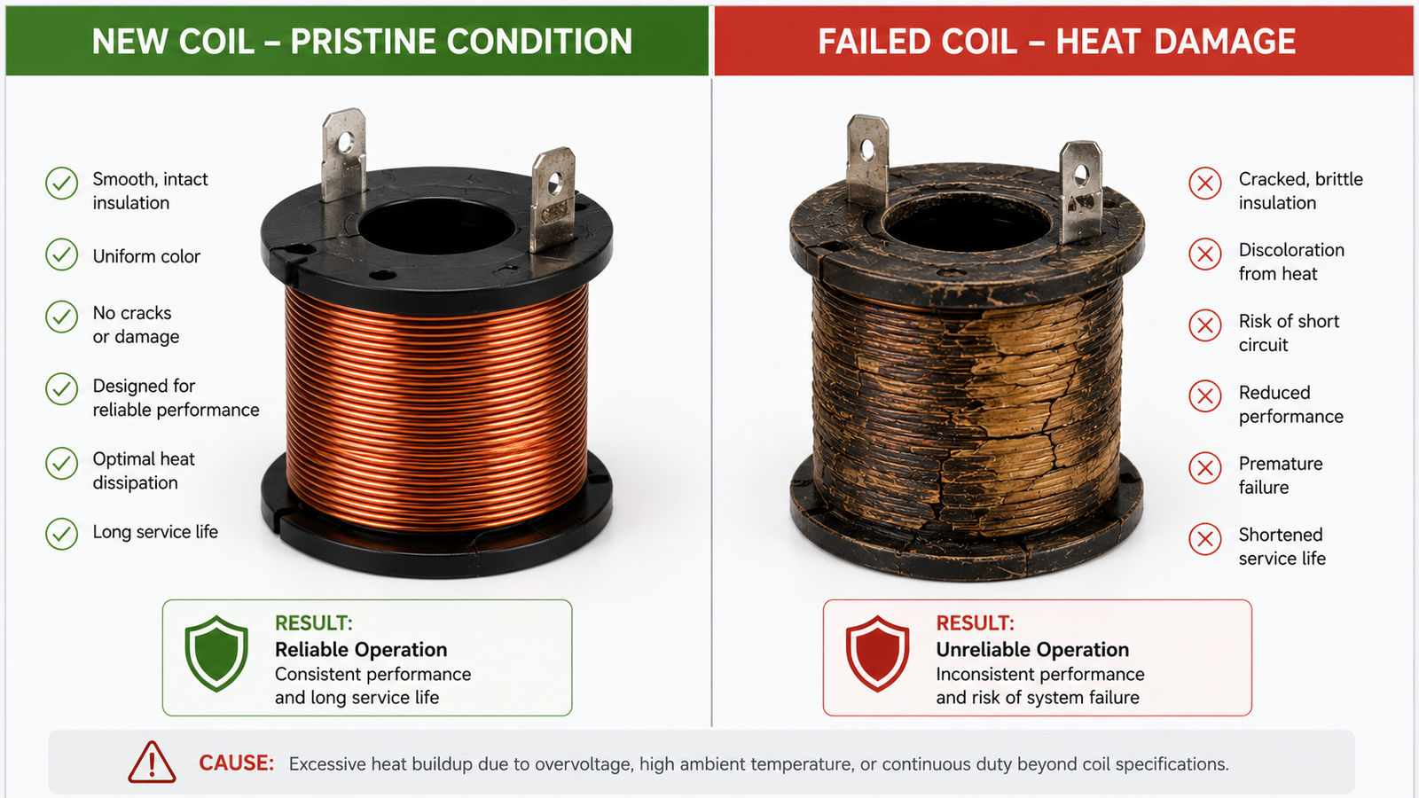
- Insulation, plastic, seals, and encapsulation operate closer to their limits.
- Material aging can accelerate.9
- Long-term reliability can decline.
This article does not diagnose failed coils. I cover that subject separately in Why Is Your Solenoid Coil Burning Out?. I also discuss service-life variables in How Long Does a Solenoid Coil Actually Last?.
Why must engineers verify hot-state magnetic force?
For a common constant-voltage DC coil, copper resistance rises as winding temperature rises.10 The current generally falls when the applied voltage remains constant.11 That change can reduce available ampere-turns and magnetic-force margin.12
The exact effect depends on the magnetic circuit, stroke, air gap, voltage, winding design, and load. Engineers should not assume that a coil’s force falls by a universal percentage.
The essential conclusion is more practical:
Cold-state pull-in success does not prove that the solenoid meets its duty requirement.
A solenoid may actuate strongly during the first cold cycle and then lose margin after repeated operation. The system may become sensitive to low supply voltage, friction, spring variation, contamination, or pressure differential.
Engineers should ask two hot-state questions:
- Can the solenoid pull in reliably at the relevant hot condition and minimum voltage?
- Can the solenoid hold reliably at the relevant temperature and mechanical load?
The test should use the real stroke and air gap. A closed-plunger holding test does not prove pull-in performance across the full working stroke.
Why does ambient temperature change the result?
A 50% rating at 20°C in an open laboratory is not thermally equivalent to 50% operation at 50°C inside an enclosed machine beside a hot valve. The hotter application begins with less available thermal margin and may dissipate heat more slowly.
I explain this variable further in How Ambient Temperature Affects Solenoid Coil Selection. For application approval, buyers should request qualified engineering evaluation rather than relying on a room-temperature datasheet value.
Is a 100% Duty Solenoid Always Better?
No. Specifying a continuous duty coil can sound like the safest procurement choice, but that assumption can create unnecessary design constraints. Continuous operation is a functional requirement, not a universal performance upgrade. The correct choice must satisfy the required time, temperature, size, force, energy, and cost targets.
A 100% duty solenoid is appropriate when the application requires sustained energization without relying on OFF-time cooling. It is not automatically stronger, smaller, cooler, or more efficient. A controlled intermittent design may provide a better force-to-size result when maximum ON time, minimum OFF time, and thermal limits are clearly defined.

Magnetic force
An intermittent application can sometimes permit higher short-term electrical loading because the OFF period provides thermal recovery. That approach may support:
- Higher short-term magnetic force
- Better short-duration pull-in performance
- A favorable force-to-package-size balance
The correct statement is not “intermittent solenoids are stronger.” The defensible statement is:
Intermittent duty can allow higher short-term magnetic performance when ON time, OFF time, and thermal limits are properly controlled.
Force still depends on the complete electromagnetic design, including winding, magnetic material, geometry, stroke, air gap, and applied voltage.
Package size
A requirement for high force and continuous energization may demand more winding volume, improved heat transfer, a different magnetic structure, or more space around the assembly. A smaller coil may still achieve the target, but engineers need thermal and force evidence rather than assumptions.
Duty rating results from the complete electromagnetic and thermal design. Engineers should not reduce it to simplistic rules about wire thickness or turn count. Our Solenoid Coil Design Guide addresses the broader design inputs without treating one winding feature as the rating.
Power consumption
Power consumption becomes especially important when many coils remain energized for hours. The electrical load can affect machine energy use, power-supply sizing, cabinet heat, and operating cost.
Some systems use a higher pull-in level followed by a lower holding level. That pull-in/hold strategy can reduce sustained power, but it requires coordinated coil, driver, timing, and force validation. Engineers should not apply voltage reduction without confirming reliable hot-state holding.
Temperature rise
A continuous duty coil must be evaluated at its relevant stabilized or near-stabilized hot condition. A five-minute test does not establish continuous capability if the product requires much longer to approach thermal equilibrium.
The test also needs the actual assembly. A coil on a metal valve can behave differently from an unmounted sample. A warm valve can add heat, while a large cool metal body can improve heat dissipation.
Cost and design complexity
A 100% ED design is not automatically more expensive. Cost depends on production volume, materials, tooling, tolerances, testing, and the existing product platform.
However, forcing a continuous rating into an application that only needs short pulses can introduce unnecessary:
- Package volume
- Material use
- Thermal design constraints
- Power limitations
- Qualification work
- Unit cost
Continuous duty is a design requirement—not automatically a performance upgrade.
I therefore advise buyers: Do not specify 100% ED simply because it sounds safer. Specify the operating profile first, and then let qualified engineers compare suitable continuous and intermittent solutions.
How Should Engineers Choose and Validate the Right Solenoid Duty Cycle?
Datasheet labels cannot replace an operating profile. Engineers need a repeatable selection process that connects machine timing to temperature and force. I use the following sequence because it exposes abnormal modes, thermal inputs, and hot-state risks before tooling or mass production begins.
Engineers should define the longest credible ON time and shortest credible OFF time, calculate the duty percentage, and record cycle duration and switching frequency. They should then add the worst thermal environment, voltage range, stroke, air gap, and force demand before validating the chosen solenoid in a representative hot-state assembly.

Step 1: Find the maximum ON time
Engineers should begin with the longest credible energization period, not the average solenoid ON time.
I review every operating mode, including:
- Normal automatic operation
- Machine startup
- Extended holding
- Manual or service mode
- Diagnostic mode
- Jam or obstruction condition
- Controller or sensor delay
- Operator error that the design reasonably permits
A normal production cycle may energize the coil for only two seconds, while manual mode keeps it energized for one minute. The one-minute condition can govern thermal selection even when operators use it infrequently.
Step 2: Find the minimum OFF time
Engineers should identify the shortest real cooling period between energization events. They should not use an ideal sequence if the controller can restart immediately or compress the OFF period during high-speed production.
The minimum OFF time indicates how much thermal recovery is available before the next cycle. It must also remain consistent with the selected coil’s rating.
Step 3: Calculate the percentage
Engineers can then apply:
Duty Cycle = ON Time ÷ (ON Time + OFF Time) × 100%
The result helps classify nominal loading, but the selection process must not stop here. The same result can represent very different thermal patterns.
Step 4: Record cycle time and switching frequency
The specification should record:
- ON time
- OFF time
- Complete cycle time
- Operations per minute or hour
- Number of consecutive cycles
- Rest periods between production batches
Switching frequency helps suppliers reproduce the heating pattern. It also prevents confusion between occasional long cycles and frequent short cycles.
Step 5: Add the thermal environment
Engineers should document the worst credible thermal condition:
- Ambient temperature
- Valve-body temperature
- Media temperature
- Enclosure and ventilation
- Nearby motors, heaters, or process lines
- Mounting contact and orientation
- Starting temperature after machine warm-up
Procurement teams should ask the supplier to state which of these conditions its solenoid ED rating covers.
Step 6: Add electrical and magnetic requirements
The same timing profile can require different coil designs when voltage, stroke, or force changes. Engineers should define:
- Nominal voltage
- Minimum and maximum voltage at the coil
- AC or DC supply and applicable drive method
- Stroke
- Initial and final air gap
- Required pull-in force
- Required holding force
- Spring load
- Friction and tolerance
- Pressure differential
- Mechanical return requirement
A complete specification lets the supplier balance thermal performance with force margin. It also provides a basis for inspection, sample approval, and design-change control.
Solenoid duty-cycle selection checklist
| Parameter | What to Check | Why It Matters |
|---|---|---|
| Maximum ON time | Longest energization | Peak heating |
| Minimum OFF time | Shortest cooling period | Thermal recovery |
| Duty cycle | ON time ÷ total cycle | Nominal loading |
| Cycle time | Complete cycle duration | Same ED can behave differently |
| Switching frequency | Operations per hour | Thermal pattern |
| Ambient temperature | Worst environment | Thermal margin |
| Valve temperature | Heat entering coil | Starting temperature |
| Voltage range | Actual minimum and maximum | Heating and force |
| Stroke / air gap | Real movement | Magnetic requirement |
| Required force | Pull-in and holding | Magnetic margin |
| Mechanical load | Spring, friction, pressure | Actual force demand |
| Mounting | Real assembly | Heat dissipation |
| Hot-state validation | Test after heating | Confirms performance |
Example 1: A pneumatic valve energized for several hours
Consider this requirement:
- 24 VDC supply
- Four to six hours energized
- 40°C ambient
- Enclosed machine
- Warm valve body
A 100% ED continuous duty solenoid should be the starting point because the application cannot depend on regular OFF periods for cooling.
However, the 100% label does not finish the evaluation. Engineers should verify:
- Stabilized or relevant long-duration temperature
- Actual maximum applied voltage
- Hot-state pull-in at minimum voltage
- Holding-force margin
- Valve-body temperature
- Real mounting and enclosure
- Pressure and mechanical load
Our Pneumatic Solenoid Coil Selection Guide covers the wider valve-specific selection process. For this decision, the essential task is to confirm continuous thermal and magnetic performance in the representative valve assembly.
Example 2: A short-pulse solenoid
Consider a second profile:
- 0.5 second ON
- 20 seconds OFF
- Approximately 2.4% duty
This application should not automatically be designed around 100% ED. A controlled intermittent duty coil may better support the short-term force requirement or package target.
Engineers must still investigate:
- Maximum credible ON time
- Abnormal extended energization
- Ambient and starting temperature
- Actual stroke and air gap
- Required pull-in force
- Minimum OFF time
- Repetition during peak production
The control system also matters. If a software fault can hold the coil energized, engineers must decide whether protection, current limiting, a timeout, or a different coil rating is required. That choice requires an application-specific safety and risk review.
Example 3: An OEM machine with multiple operating modes
Consider a machine with these three modes:
| Mode | ON Time | OFF Time | Nominal Pattern |
|---|---|---|---|
| Normal | 2 s | 8 s | 20% |
| Startup | 10 s | 5 s | 66.7% |
| Manual | 60 s | — | Continuous for 60 s |
An average based on production time could make this application appear lightly loaded. However, the startup sequence creates much higher cyclic loading, while manual mode introduces a long uninterrupted energization period.
Engineers should not design from the average duty cycle.
Instead, they should design and validate against the worst credible operating profile. The correct solution may be a continuous duty coil, an intermittent design with controlled limits, or a pull-in/hold control strategy. The decision depends on hot-state force, temperature, package size, and risk controls.
In OEM reviews, I often find that manual and service modes are documented later than normal production timing. I prefer to identify them before prototype approval because a hidden long-ON condition can invalidate an otherwise reasonable coil selection.
Four common selection mistakes
-
“The same duty percentage means the same thermal condition.”
This statement is wrong because maximum ON time and cycle duration change the heating pattern. -
“100% ED is always safer and better.”
This statement is wrong because continuous capability may introduce unnecessary trade-offs without improving application performance. -
“Cold pull-in means the design is validated.”
This statement is wrong because current and force margin can change after the winding heats. -
“Intermittent duty is mainly a cheaper design.”
This statement is wrong because intermittent duty can be a deliberate force, size, and thermal optimization.
How should hot-state validation be performed?
The final decision cannot remain theoretical. Engineers should test production-representative samples with the real or accurately simulated assembly.
The validation plan should cover:
- Maximum voltage for the thermal condition
- Minimum voltage for the pull-in condition
- Maximum ON time
- Minimum OFF time
- Worst specified ambient
- Actual valve-body temperature
- Real mounting and enclosure
- Mechanical spring and friction loads
- Relevant pressure differential
- Manufacturing tolerances
- Multiple samples from representative production
A continuous duty coil should be tested toward its relevant stabilized thermal condition. An intermittent duty coil should be cycled until it establishes a repeatable thermal pattern. Engineers should record winding or representative coil temperature through a suitable validated method and verify actuation throughout the test.
The acceptance criteria should cover more than insulation survival. They should include:
- Reliable hot-state pull-in
- Adequate holding margin
- Release performance where relevant
- Temperature within approved material and product limits
- No unacceptable dimensional or functional changes
- Repeatable results across samples
The real question is not whether the solenoid works during the first few cycles. The question is whether it retains sufficient thermal and magnetic margin at the actual operating condition.
For regulated or safety-relevant equipment, buyers should involve qualified electrical, mechanical, and compliance professionals. They should also verify current supplier test reports, material declarations, certification documents, and applicable standards rather than relying only on catalog claims.
Frequently Asked Questions
What does 100% duty cycle mean on a solenoid?
A 100% duty cycle means the solenoid can remain continuously energized under the manufacturer’s specified voltage, ambient temperature, mounting, and thermal conditions. It does not mean that the coil can run indefinitely at any voltage or temperature. Engineers must verify the rating in the actual valve, enclosure, and hot-state application.
What does 25% ED mean?
A 25% ED rating means the coil is energized for 25% of a defined operating cycle. For example, five seconds ON and 15 seconds OFF equals 25%. Engineers must also obtain the maximum ON time, minimum OFF time, and reference cycle. The rating does not permit every possible 25% timing combination.
Can a continuous-duty solenoid run all day?
A continuous duty solenoid can generally remain energized for long periods when it operates within its documented conditions. Engineers must confirm voltage, ambient and valve temperatures, mounting, enclosure, and load. They should validate the relevant stabilized temperature and hot-state force rather than assuming that a 100% ED label covers every installation.
Can I replace an intermittent-duty coil with a continuous-duty coil?
A continuous coil is not automatically a direct replacement. The new coil must match voltage, dimensions, connector, stroke, air gap, magnetic force, valve interface, holding requirements, and environmental limits. Engineers should also check whether the change affects response, power, certifications, and control behavior before approving the replacement.
Can an intermittent-duty solenoid produce more force?
An intermittent design can permit higher short-term electrical loading when its ON time, OFF time, and thermal limits are controlled. That approach may improve short-term magnetic performance or force-to-size balance. However, intermittent coils are not universally stronger. Actual force depends on voltage, winding, magnetic structure, air gap, stroke, and temperature.
Why can two 10% duty applications behave differently?
Two 10% applications can use different timing patterns, such as one second ON and nine seconds OFF versus 60 seconds ON and 540 seconds OFF. The longer uninterrupted ON period may produce a higher peak temperature before cooling begins. Coil construction, mounting, valve temperature, airflow, and enclosure conditions can increase that difference.
Conclusion
Engineers should not select a solenoid duty cycle from percentage alone. They should start with maximum ON time, minimum OFF time, cycle duration, switching frequency, thermal environment, voltage, stroke, and required magnetic force. They should then validate the solenoid at the relevant hot-state operating condition.
For OEM projects, we recommend selecting the duty rating against the worst credible operating profile, with adequate thermal and magnetic margin—not simply specifying 100% ED by default. Contact SolenElec to review your timing profile, force requirements, assembly conditions, and customized solenoid coil specification before prototype or mass-production approval.
"Motor Duty Cycles Explained: S1–S8 Classifications & Guide", https://www.kebamerica.com/blog/4-types-of-motor-duty-cycles-every-engineer-should-know/. Duty-type standards and technical summaries for electrical machines classify operation by time sequence and thermal behavior, supporting the need to specify timing as well as an energized ratio. Evidence role: expert_consensus; source type: institution. Supports: The source should show that duty classifications use not only a percentage but also operating sequence, duration, or cycle information.. Scope note: Many formal duty-type standards are written for rotating electrical machines, so their use for solenoids is contextual rather than product-specific. ↩
"Duty cycle", https://en.wikipedia.org/wiki/Duty_cycle. A general electronics definition describes duty cycle as the proportion of a period for which a signal or device is active, supporting the use of ON time divided by total cycle time for solenoid energization. Evidence role: definition; source type: encyclopedia. Supports: The source should define duty cycle as the fraction or percentage of one period during which a device or signal is active.. Scope note: The source may define duty cycle generally rather than specifically for solenoid coils. ↩
"What Is Duty Cycle in Welding Machines? | UTI", https://www.uti.edu/blog/welding/duty-cycle-in-welding-machines-what-is-it. Educational electronics references define duty cycle as active time divided by the total period, typically expressed as a percentage; this directly supports the ON-time over ON-plus-OFF-time formula. Evidence role: definition; source type: education. Supports: The source should state the standard duty-cycle formula as active time divided by period, usually expressed as a percentage.. ↩
"Solenoid Coil Burning Out: Why Does It Happen? Causes ...", https://solenelec.com/why-is-your-solenoid-coil-burning-out-a-troubleshooting-guide-to-preventing-failure/. Transient heat-transfer theory shows that component temperature depends on heating duration, cooling duration, and thermal time constants, which supports the statement that equal duty percentages can produce different coil temperature patterns. Evidence role: mechanism; source type: education. Supports: The source should explain that temperature rise in an electrical component under pulsed heating depends on time constants and the duration of heating and cooling intervals, not only average duty percentage.. Scope note: This is contextual support from thermal analysis and may not be a direct solenoid-specific test result. ↩
"10 CFR Appendix B to Subpart B of Part 431 - Uniform Test Method ...", https://www.law.cornell.edu/cfr/text/10/appendix-B_to_subpart_B_of_part_431. IEC-style duty classifications define S1 continuous duty as operation at a constant load for a duration sufficient to reach thermal equilibrium, supporting the article’s description of sustained energization approaching a stable thermal condition. Evidence role: definition; source type: institution. Supports: The source should define S1 continuous duty as operation at constant load for sufficient time to reach thermal equilibrium.. Scope note: The standard terminology is most commonly published for electric machines, so it provides contextual terminology for solenoid applications. ↩
"IEC 60034-1 Duty Cycles", https://avsld.com.sg/iec-duty-cycles/. Standard duty classifications describe S2 short-time duty as operation for a specified duration that is insufficient to reach thermal equilibrium, followed by rest and cooling, supporting the article’s explanation. Evidence role: definition; source type: institution. Supports: The source should define S2 as short-time duty where operation is not long enough to reach thermal equilibrium, followed by rest sufficient for cooling.. Scope note: The definition is a general electrical-machine duty classification and may need manufacturer interpretation for a specific solenoid. ↩
"Ten different duty types (load cycle) of a three-phase ...", https://electrical-engineering-portal.com/10-duty-types-three-phase-asynchronous-motors. Duty-classification references define S3 intermittent periodic duty as repeated cycles of operation and rest, which supports the article’s characterization of repeated ON and OFF periods. Evidence role: definition; source type: institution. Supports: The source should define S3 intermittent periodic duty as a sequence of identical cycles with operating and rest periods.. Scope note: The reference may address electric motors rather than solenoid coils, so it supports the terminology by analogy. ↩
"How Should You Design a Coil for Better Performance and Long ...", https://solenelec.com/how-should-you-design-a-coil-for-better-performance-and-long-term-reliability/. The principle of Joule heating states that current through an electrical resistance dissipates power as heat, supporting the claim that an energized winding generates heat during the ON period. Evidence role: mechanism; source type: education. Supports: The source should explain Joule heating, where current through resistance produces heat in a conductor or winding.. ↩
"Lifetime Prediction Methods for Degradable Polymeric Materials—A ...", https://pmc.ncbi.nlm.nih.gov/articles/PMC7599543/. Thermal-aging studies of electrical insulation and polymers commonly model degradation rate as increasing with temperature, supporting the claim that higher coil operating temperatures can accelerate material aging. Evidence role: mechanism; source type: paper. Supports: The source should show that elevated temperature accelerates aging or degradation rates in electrical insulation or polymer materials, often modeled with Arrhenius behavior.. Scope note: The source may not test the exact solenoid materials used in a given product, so it supports the general aging mechanism rather than a specific life prediction. ↩
"Thermal conductivity and resistivity - Wikipedia", https://en.wikipedia.org/wiki/Thermal_conductivity_and_resistivity. Material-property data for copper show a positive temperature coefficient of electrical resistance, supporting the statement that a copper solenoid winding’s resistance rises as it becomes hotter. Evidence role: mechanism; source type: government. Supports: The source should provide copper’s positive temperature coefficient of resistance or explain that copper resistivity increases with temperature.. ↩
"20. Ohm's Law: Resistance and Simple Circuits", https://openbooks.lib.msu.edu/collegephysics2/chapter/ohms-law-resistance-and-simple-circuits-2/. Ohm’s law expresses current as voltage divided by resistance, supporting the inference that current falls in a constant-voltage DC winding when resistance increases. Evidence role: mechanism; source type: education. Supports: The source should state Ohm’s law and show that, at constant voltage, current is inversely related to resistance.. Scope note: This directly applies to steady DC resistance and does not account for all transient or driver-controlled coil behaviors. ↩
"Solenoid", https://en.wikipedia.org/wiki/Solenoid. Electromagnetic theory relates magnetomotive force to ampere-turns and solenoid force to the resulting magnetic field and air-gap conditions, supporting the claim that reduced current can reduce magnetic-force margin. Evidence role: mechanism; source type: education. Supports: The source should explain that magnetomotive force is proportional to ampere-turns and that solenoid or electromagnet force depends on magnetic circuit conditions and current.. Scope note: The exact force change is design-specific and cannot be inferred from current alone without the full magnetic geometry. ↩