Your products are failing in the field, and the cause is a burnt-out solenoid coil. This increases warranty costs, damages your brand, and creates a supply chain nightmare.
The truth is, 90% of solenoid coil burnouts are not because they were "used up." The problem was built-in during the design and manufacturing stages. The failure is almost always due to flaws in thermal design, material selection, or a misunderstanding of the application. It's a preventable system error.
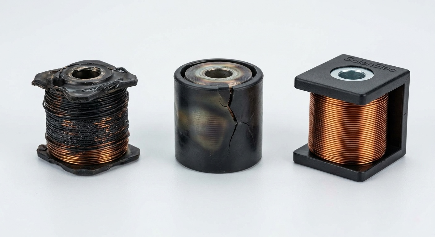
I’ve spent over 20 years manufacturing solenoid coils, and I’ve seen it all. A burnt coil isn't just a component failure; it’s a symptom of a deeper issue. Too many brands face this problem because they treat the coil as a simple commodity. But a coil failure is never an accident. It's a predictable outcome of specific oversights. Let's break down the real reasons your coils are failing, so you can stop it from happening.
Voltage Fluctuations: Is Your Power Supply Killing Your Coil?
You assume your power supply is stable, but even small voltage swings can be fatal for a solenoid coil. This leads to random failures that are incredibly difficult to diagnose.
Yes, an unstable power supply is a primary cause of burnout. Overvoltage forces excessive current through the coil, causing it to overheat and fail quickly. Undervoltage can prevent the plunger from seating, trapping the coil in a high-current state that also leads to rapid burnout.
A solenoid coil is designed to operate within a specific voltage range, usually around ±10%. When the power supply moves outside this range, things go wrong fast. It’s not just about dramatic spikes; even subtle, consistent variations can degrade the coil over time and lead to failure. We see this often with clients whose end-product is used in regions with less stable power grids. The coil gets the blame, but the root cause is the electrical environment it's forced to operate in.
The Danger of Overvoltage
When the voltage is too high, the current flowing through the coil increases according to Ohm's law (I = V/R). Since the coil's resistance is fixed, more voltage means more current. Power, which generates heat, is calculated as P = I²R. So, a small increase in voltage leads to a much larger increase in heat. This excess heat breaks down the wire's enamel insulation, causing a short circuit between the windings. The result is a dead coil.
The Hidden Risk of Undervoltage
Undervoltage seems less dangerous, but it can be just as destructive. A solenoid needs a strong magnetic field to pull the plunger in. This requires a high "inrush" current. Once the plunger is seated, the air gap in the magnetic circuit1 closes, and the current drops to a much lower "holding" level. If the voltage is too low, the magnetic force might not be strong enough to pull the plunger in completely. The coil then stays stuck in its high-current inrush state, generating massive amounts of heat and burning out in minutes.
| Voltage Condition | Plunger Action | Current State | Heat Generation | Result |
|---|---|---|---|---|
| Overvoltage | Actuates too forcefully | Higher than normal | Excessive | Insulation breakdown, short circuit |
| Correct Voltage | Normal actuation | Inrush, then holding | Normal | Long operational life |
| Undervoltage | Fails to actuate fully | Stays in high inrush | Extreme | Rapid burnout |
The Overheating Factor: Common Causes of Thermal Failure in Solenoids?
Your coils feel hot, but you figure it’s normal. But that heat is a silent killer, slowly degrading the coil until it suddenly fails, often without any obvious warning.
The most common causes of overheating are high ambient temperatures2, poor heat dissipation3 in the final assembly, and incorrect winding design. When the coil's temperature exceeds its insulation class4 rating, the wire's enamel coating fails, leading to a short circuit and burnout.
In my experience, thermal design is the single most underestimated factor in solenoid reliability. I’ve seen countless projects from international clients that work perfectly in a controlled lab environment. But as soon as they go to mass production, the burnout reports start flooding in. The reason is almost always simple: the thermal design was flawed. The engineers only considered the rated voltage, not the ambient temperature or how the coil was mounted.
The Winding Density Trap
To get more magnetic force from a small coil, designers are tempted to pack in as many windings as possible. But this high density makes it very difficult for heat to escape from the inner layers. The core of the coil can become a hot spot that far exceeds the temperature on the surface. At our factory, we use micron-level tension control during winding. We would rather sacrifice a tiny bit of magnetic force than let the temperature rise cross the line. This is our non-negotiable rule for long-term reliability.
Heat Dissipation is Not Optional
A solenoid coil doesn't exist in a vacuum. It’s part of a larger assembly, often a valve body. If that assembly acts as a heat sink, great. But if it traps heat, it will accelerate the coil's death. The material it touches, the airflow around it, and the temperature of the fluid it controls all contribute to the final operating temperature. A coil that is safe at 20°C ambient temperature might fail quickly at 60°C.
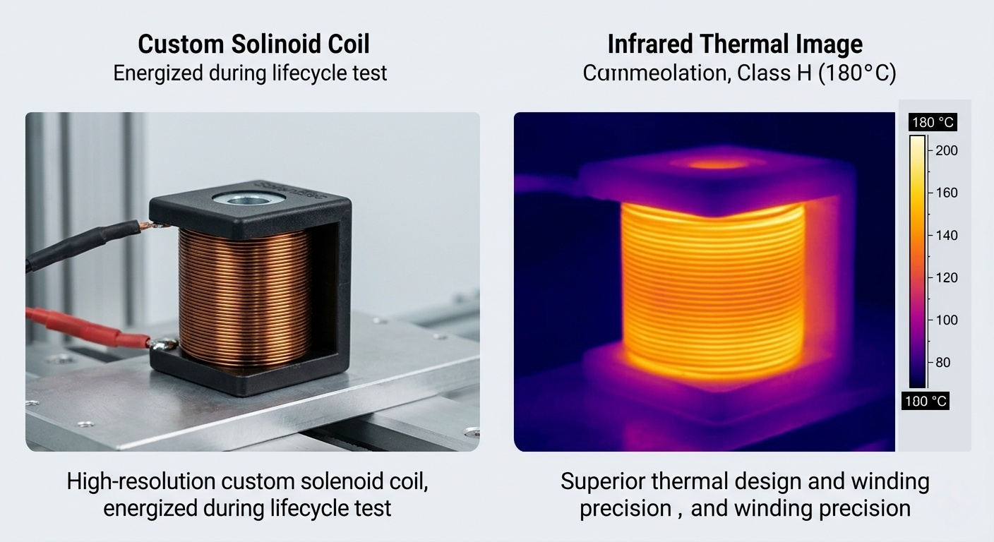
Here are the standard insulation class4es. Exceeding these temperatures guarantees failure.
| Insulation Class | Maximum Temperature | Common Materials |
|---|---|---|
| Class A | 105°C | Organic materials like cotton, silk, paper |
| Class B | 130°C | Inorganic materials like mica, fiberglass with binders |
| Class F | 155°C | Class B materials with higher-temp binders |
| Class H | 180°C | Silicon elastomers, combinations of mica/fiberglass |
Mechanical Obstructions: How a Stuck Plunger Leads to Coil Burnout?
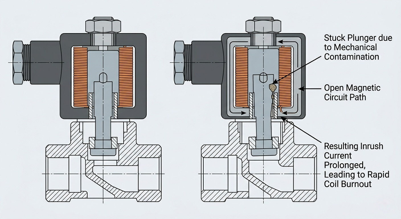
The valve is sticking, so you assume it’s a mechanical problem. But that stuck plunger is not just a mechanical issue; it can electrically destroy a perfectly good coil in minutes.
When a plunger is blocked and cannot complete its stroke, the coil never switches from its high "inrush" current to its low "holding" current. This prolonged high-current state generates extreme heat, melting the wire's insulation and burning out the coil very quickly.
This brings me to another critical insight: you must understand the application. A solenoid coil is not a standard, off-the-shelf part. Its design is completely dependent on the valve body, the plunger it moves, and the job it has to do. A coil designed for a fast-acting air valve will fail if you put it on a slow-moving hydraulic valve, even if the voltage is the same. The magnetic circuit1 is different, and the forces required are different.
Inrush vs. Holding Current
When you first power a solenoid, it draws a high inrush current to create a powerful magnetic field to pull the plunger across an air gap. This takes a lot of energy. Once the plunger seats, the air gap is gone, and the magnetic circuit1 becomes much more efficient. The current then drops to a low holding level, just enough to keep the plunger in place. An inrush current can be 5 to 10 times higher than the holding current. The coil is designed to handle this spike for only a fraction of a second. If a mechanical issue prevents the plunger from seating, that high current never drops.
It's a System Failure
I've had clients send me burnt coils and ask us to "rewind" them. That's the wrong approach. Our first question is always: "What is it connected to?" We don't just fix the coil; we analyze the system. We recalculate the magnetic circuit1 and adjust the manufacturing process to match the mechanical load. Our goal is to eliminate the failure mode before it ever reaches mass production. A stuck plunger can be caused by:
- Debris or contamination in the valve
- Swelling of seals
- Incorrect fluid viscosity
- Wear and tear on mechanical parts
- Poor alignment during assembly
Burnout from a stuck plunger isn't an electrical accident; it's a systemic failure.
Environmental Impact: The Role of Moisture and Chemicals in Insulation Breakdown?
Your product passes every test in your clean, dry factory. But once it’s installed in a humid kitchen or a factory with chemical fumes, the coils start to fail.
Yes, environmental factors5 like moisture, humidity, and chemicals are silent killers. They attack the coil's encapsulation and wire insulation, creating microscopic pathways for electricity to short-circuit between the windings. This leads to a gradual breakdown and eventual burnout.
This is where skimping on materials will come back to haunt you. The grade of the copper wire, the thickness of its enamel coating, the heat resistance of the plastic bobbin, and the quality of the final encapsulation or varnish—if you compromise on any one of these, you cut the coil's lifespan in half. I learned this lesson the hard way years ago. We had a coil with a stable, low failure rate. Then, for one batch, the failure rate doubled. The specs were identical. The problem? The supplier had changed their source for copper wire. From that day on, we implemented a strict rule: all raw materials must be fully traceable. We don't accept vague parameters or "equivalent" materials.
The Material Bill of Health
A coil is a system of materials working together. Each one has a role in protecting the windings from the outside world.
- Magnet Wire: The purity of the copper and the quality of the enamel insulation determine its resistance to heat and electrical stress.
- Bobbin: This plastic frame must withstand the maximum operating temperature without deforming or releasing chemicals that could harm the enamel.
- Encapsulation: The epoxy or thermoplastic overmolding6 is the coil's armor. It must be void-free and properly bonded to keep moisture and contaminants out.
Choosing the Right Protection
The type of protection needed depends entirely on the end-use environment. A coil for a coffee machine inside a home needs a different level of protection than one used in an industrial dishwasher or an outdoor irrigation system.
| Encapsulation Type | Pros | Cons | Best For |
|---|---|---|---|
| Epoxy Potting | Excellent chemical/moisture resistance. | Brittle, can crack under thermal shock. | Harsh chemical environments. |
| Thermoplastic Overmolding | Durable, good impact resistance, fast cycle time. | Lower temperature limits than some epoxies. | High-volume home appliances. |
| Varnish Dip | Low cost, good for heat dissipation3. | Minimal physical or moisture protection. | Dry, controlled environments. |
Duty Cycle7 Mismatch: Are You Overworking Your Solenoid?
You bought a solenoid coil rated for 230V, and you're running it at 230V. So why does it keep burning out after just a few hours of use?
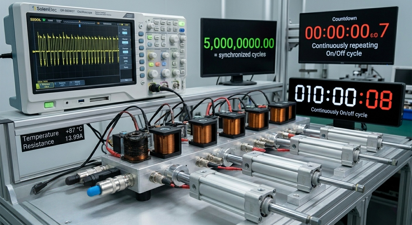
You are almost certainly using an intermittent-duty coil8 in a continuous-duty application. Intermittent coils are designed for short "on" cycles followed by long "off" cycles to cool down. If you leave one energized constantly, it cannot dissipate the heat and will overheat and fail.
This is another classic case of a simple misunderstanding leading to catastrophic failure. Many procurement managers look only at the voltage and physical size. They don't ask about the duty cycle. But this parameter is just as important as voltage. It defines how the coil is designed to be used and, specifically, how it is designed to manage heat.
Continuous vs. Intermittent Duty
- Continuous Duty (100% Duty Cycle7): These coils are designed to be left on indefinitely without overheating. They are wound with thinner wire and more turns to increase resistance and limit current, or they have a more robust thermal design to dissipate heat effectively.
- Intermittent Duty (<100% Duty Cycle7): These coils are designed for brief periods of activation. They often use thicker wire to generate a stronger magnetic field quickly, but they produce more heat. They rely on a subsequent "off" period to cool down. If that cool-down period doesn't happen, the heat builds up until the coil fails.
Duty cycle is calculated as a percentage: [Duty Cycle](https://arxiv.org/pdf/2507.22740)7 % = (On Time / (On Time + Off Time)) * 100.
The Application Conversation
This is why our first conversation with a new client is always about the application. We ask:
- How long will the coil be energized at one time?
- How long will it be off before it is energized again?
- What is the maximum ambient temperature?
An intermittent-duty coil8 is not a "cheaper" version of a continuous-duty one; it's a different tool for a different job. Using an intermittent coil for a continuous application is like trying to drive a nail with a screwdriver. It's the wrong tool, and the result will be failure. You can always use a 100% duty cycle coil in an intermittent application, but you can never do the reverse. Getting this right at the specification stage is one of the easiest ways to prevent burnout.
Conclusion
Solenoid coil burnout is not random. It is a system failure9 caused by design flaws, poor material choices, or a mismatch with the application. The solution is working with a partner who understands this.
Understanding magnetic circuits helps optimize solenoid coil design, preventing failures and enhancing reliability in various applications. ↩
Learn how high ambient temperatures can degrade solenoid coils and lead to premature failure. ↩
Understand the role of heat dissipation in preventing solenoid coil burnout and ensuring reliability. ↩
Explore the different insulation classes and their temperature limits to prevent solenoid coil failure. ↩
Understand how moisture, humidity, and chemicals can lead to solenoid coil insulation breakdown. ↩
Learn about the advantages of thermoplastic overmolding in protecting solenoid coils. ↩
Understanding duty cycles helps prevent coil burnout by matching the coil's design to its application, ensuring longevity and reliability. ↩
Understanding intermittent-duty coils helps prevent burnout by matching the coil's duty cycle to its application, ensuring optimal performance and longevity. ↩
Learn how solenoid coil burnout is often a symptom of broader system failures and how to address them. ↩