
Solenoid Valve Coil Replacement: A Drop-In Compatibility Checklist
A solenoid coil replacement can look correct on a pneumatic valve and still create a hidden production or field-service problem. I have seen buyers focus on a 24V marking and tube diameter, only to face overheating, weak hot-state pull-in, or connector faults after assembly. A disciplined compatibility checklist prevents those risks.
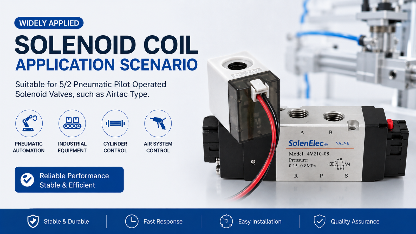
A solenoid coil replacement is truly drop-in only when it matches the existing pneumatic valve in mechanical fit, electrical architecture, connector behavior, magnetic performance, and thermal duty.1 Voltage and tube diameter are only two checks. If any critical requirement changes, I treat the coil as a redesign that requires engineering validation rather than a direct replacement.
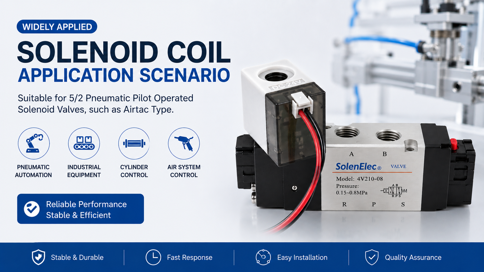
For procurement teams and pneumatic OEMs, the goal is not to find a coil that merely slides onto an armature tube. I recommend proving that the candidate coil performs consistently on the real valve, under the real voltage, temperature, wiring, and duty conditions of the application.
What Does “Drop-In” Mean for a Solenoid Coil Replacement on Pneumatic Valves?
A failed coil can stop production, while an unverified replacement can create a more expensive problem later. The temptation is understandable: the old part says 24V, the replacement says 24V, and both appear to use a similar connector. I do not consider that enough evidence.
For pneumatic valves, a drop-in solenoid coil replacement must reproduce the original coil’s form, fit, electrical load, magnetic force, connector interface, and thermal behavior without requiring changes to the valve body, cabinet wiring, driver output, or assembly process. A visual match alone does not establish compatibility.

Form, Fit, and Function Must All Match
I use the phrase form, fit, and function because it captures the difference between a part that appears compatible and a part that is approved for use.
- Form includes the outer envelope, bore diameter, height, shoulder position, nut interface, and connector geometry.
- Fit means the coil seats correctly on the existing armature tube and clears adjacent valves, brackets, leads, and manifold components.
- Function includes pull-in force, holding performance, release behavior, power consumption, temperature rise, and electrical interface behavior.
A coil can pass the first two categories but fail the third. For example, a lower-power winding may physically fit the valve and reduce heat. However, it may also provide insufficient ampere-turns to pull in the armature at the lowest available terminal voltage.2
Replacement of a Failed Coil Is Not a Blind Copy Exercise
When I review a failed pneumatic solenoid coil replacement project, I first ask why the original coil failed. A burned coil may indicate more than a winding issue.3 The underlying cause may be:
- Incorrect supply voltage
- AC/DC mismatch
- A stuck valve armature or contaminated valve internals
- Excessive ambient temperature
- Continuous energization beyond the original duty cycle
- High contact resistance in the connector
- Wrong suppression component or reversed polarity
- Tight spacing between energized valves on a valve island
A burnt coil is evidence. It is not automatically a valid master sample for a replacement specification.
OEM Second-Source Expectations Are Higher
For one-off maintenance, a buyer may focus on restoring operation quickly. For an OEM introducing a second source, I recommend a higher standard. The replacement coil should have repeatable dimensions, controlled winding resistance at 20°C, stable encapsulation, consistent connector details, and batch traceability.
At SolenElec, we approach OEM/ODM coil discussions as an engineering verification task. Our production systems include process traceability and outgoing inspection practices, but I still recommend that buyers verify the documents, test data, and application fit relevant to their own valve design before approving a production change.
Which Five Gates Must a Solenoid Coil Replacement Pass Before It Is Drop-In?
A candidate coil may pass a basic dimensional check and still fail after several hours of energized operation. That outcome often happens because electrical, magnetic, and thermal requirements were assumed rather than measured. I use five gates to make the evaluation more systematic.
A solenoid coil replacement should pass five gates: mechanical fit, electrical architecture, connector and wiring compatibility, magnetic and valve-load performance, and thermal/environmental suitability. I classify a candidate as drop-in only when all five gates pass on the existing pneumatic valve and under representative operating conditions.

Gate 1: Mechanical Fit
Mechanical fit is more detailed than “the hole is the same size.” I recommend measuring the actual installed coil and the valve interface.
Key checks include:
- Bore or inner diameter
- Armature tube engagement length
- Coil height
- Shoulder or locating feature
- Nut thread, nut seating area, and torque clearance
- Outer encapsulation envelope
- Rotation clearance around the connector or lead exit
- Clearance to adjacent valves on a manifold
A coil that sits a few millimeters too high may leave an unintended air gap. That gap can reduce magnetic force significantly.4 A coil that contacts the manifold or adjacent coil may also transfer heat and create assembly stress.
Gate 2: Electrical Architecture
I next confirm the coil’s electrical design. The rated voltage is necessary, but it is not sufficient.
The electrical review should include:
| Electrical item | Why I check it |
|---|---|
| AC or DC supply | A 24VAC coil and a 24VDC coil are not interchangeable5 |
| Rated voltage | The actual system voltage may differ from the nominal value |
| Frequency for AC | 50 Hz and 60 Hz performance can differ6 |
| Rated power or current | This affects heat generation and driver loading |
| R20 resistance and tolerance | Resistance supports winding verification at a controlled temperature |
| Duty cycle | A coil suitable for intermittent duty may overheat at 100% ED7 |
| Polarity | Diodes, LEDs, and TVS suppression can make polarity critical |
For pneumatic valve coils, low-wattage designs may operate around 0.5–1.5 W, while many standard-duty designs fall roughly in the 2–4.8 W range. I do not use these bands as approval criteria. The correct power depends on the valve’s magnetic circuit, armature load, pressure conditions, ambient temperature, and required response.
Gate 3: Connector and Wiring
A DIN-style connector is not one universal interface.8 I check the exact form, pin spacing, earth contact arrangement, keying, cable exit orientation, and strain relief.
Common details include:
- DIN EN 175301-803 connector form
- Pin spacing and connector profile
- Ground or earth terminal position
- Flying-lead length and wire gauge
- Lead color identification
- Rectifier, LED, diode, or surge-suppression components
- Plug orientation on tightly packed valve islands
Gate 4: Magnetic Load and Valve Performance
The solenoid coil must generate enough magnetic force to move and hold the existing armature. I consider the armature tube, spring force, air gap, fluid or pneumatic pressure load, and hot-state winding condition.
A coil that works when cold on an unloaded bench may fail at elevated temperature or lower terminal voltage. I also check whether the valve releases correctly. Residual magnetism, incorrect coil geometry, or a changed magnetic circuit can affect release behavior and cycle consistency.
Gate 5: Thermal and Environmental Suitability
Finally, I evaluate heat. The coil’s insulation system, encapsulation material, IP expectation, ambient conditions, and adjacent-coil heating all matter.
For example, a valve island operating at 40°C ambient with several energized coils can create a much more severe condition than a single coil tested in open air at room temperature. IP ratings also depend on the complete assembly, including the correct connector, seal, cable gland, and installation orientation.9
What Looks Compatible but Is Not a Compatible Pneumatic Valve Coil?
Visual comparison encourages false confidence. I understand why it happens: buyers need a practical starting point, and many coil families share similar shapes. However, the most common compatibility indicators are often incomplete or misleading when used alone.
A compatible pneumatic valve coil cannot be confirmed by one matching feature, such as 24V, color, outer size, or a DIN-style plug. I verify the complete interface because voltage type, pinout, winding resistance, air gap, power, and heat performance can differ even when two coils look nearly identical.

| What people match | Why it is not enough | What can still break |
|---|---|---|
| Same 24V stamp | 24VAC is not the same as 24VDC; actual terminal voltage may be lower | No pull-in, overheating, driver failure |
| Same outer size | Bore, height, shoulder, and nut geometry may differ | Coil sits high, rattles, or cannot seat |
| Same DIN appearance | Form A, B, and C interfaces have different dimensions and pin arrangements | Plug does not seat, seal, or ground correctly |
| Same wattage | Magnetic force depends on ampere-turns, air gap, and valve load | Slow switching or hot-state no-pull-in |
| Same color | Color is not a controlled electrical specification | Wrong voltage installed during assembly |
| Same hot resistance reading | Resistance rises with copper temperature10 | False pass or false rejection |
| LED plug fits | LED, diode, and suppression components may have different polarity or ratings | PLC fault, no indication, coil damage |
Common Electrical Traps
The following situations deserve a redesign review rather than a quick substitution:
-
A 12V coil is installed on a 24V system.
The coil can overheat quickly because the winding receives excessive voltage. -
A 24V coil is installed on a 12V system.
The valve may fail to pull in, especially at low supply voltage or elevated temperature. -
A DC coil is substituted for an AC coil, or vice versa.
AC coils and DC coils use different electrical and magnetic design assumptions. An AC coil may buzz or overheat if it does not seat fully. A DC coil on AC may have unacceptable current behavior. -
An LED or diode connector is copied visually.
I check the polarity, LED operating range, diode orientation, and PLC output compatibility. A reverse-polarity diode can act like a short circuit. -
Power is reduced without checking force margin.
Lower wattage can reduce heat, but it may also reduce the magnetic margin needed for reliable hot-state pull-in.
I never describe a DIN solenoid coil interchange as “universal.” The valve interface and electrical architecture must be verified.
Why Hot Resistance Is a Poor Shortcut
Copper resistance changes with temperature. A coil measured after operation will show a higher resistance than the same coil at 20°C. For a controlled comparison, I use R20, meaning resistance referenced to 20°C.
A common correction method is:
[ R_{20} = frac{R_T}{1 + 0.00393(T - 20)} ]
In this relationship, (R_T) is the measured resistance at temperature (T) in °C. I recommend that engineering teams use their approved calculation method and calibrated measurement equipment. The key point is simple: compare controlled R20 values to the drawing or approved specification, not to a guessed “normal” resistance for a 24V coil.
How Should I Collect Data Before a Solenoid Coil Replacement Review?
Supplier catalogs can help narrow options, but they should not be the first source of truth. The installed valve, the original coil, and the real electrical conditions provide the data that determines whether a replacement can work safely and consistently.
I start a solenoid coil replacement review by documenting the installed coil, valve interface, connector, and actual terminal voltage. I then collect drawings, markings, measurements, and failure evidence before comparing candidate coils. This process reduces the risk of approving a visually similar but electrically unsuitable coil.

Photograph the Installed Assembly
I recommend taking clear photographs before removing the original coil. These photographs often resolve questions that a part number alone cannot answer.
Useful images include:
- Coil markings from all readable sides
- Connector face and pin arrangement
- Cable or lead exit direction
- Coil installed on the valve
- Armature tube and nut interface
- Adjacent valve spacing on the manifold
- Any visible heat discoloration, cracks, or swelling
- The control cabinet connection, where practical
I once used a photo of a valve island’s cable exit to identify a clearance problem that was not visible in the coil drawing. The candidate coil had an acceptable bore and height, but its connector exit collided with the neighboring valve assembly.
Measure the Features That Affect Fit
I recommend recording measurements with suitable calibrated tools. Buyers do not need to create a full metrology report at the first stage, but they should capture enough information for an engineering team to identify critical interfaces.
| Item to measure | Why it matters |
|---|---|
| Inner diameter or bore | Confirms armature tube compatibility |
| Overall height | Affects seating, nut engagement, and clearance |
| Outer envelope | Prevents interference with adjacent components |
| Shoulder dimensions | Supports repeatable axial location |
| Nut interface | Confirms assembly and torque clearance |
| Lead length | Affects cabinet or manifold routing |
| Terminal voltage | Confirms the electrical condition at the coil itself |
Measure Voltage at the Coil, Not Only at the Power Supply
Voltage drop matters on long cable runs, multi-valve islands, and PLC-driven systems.11 A supply may be nominally 24VDC, while the last valve on the manifold receives only 21–22V under load.
I recommend energizing the real circuit and measuring voltage directly at the coil terminals. This simple check helps reveal:
- Cable voltage drop
- Undersized conductors
- Connector contact resistance
- PLC output limitations
- Incorrect polarity on protected coils
- Differences between unloaded and loaded voltage
Use the Failed Coil as Diagnostic Evidence
The failed coil should be retained until the root cause is understood. I look for signs that can guide the engineering review:
- Burnt smell or dark discoloration: possible thermal overload, overvoltage, or continuous duty exposure
- Open circuit: possible winding break, termination issue, or thermal damage
- Swollen or cracked encapsulation: possible excessive heat or chemical exposure
- Melted connector housing: possible poor contact, high current, or incorrect connector selection
- No visible coil damage but valve does not actuate: possible valve jamming, pressure issue, or insufficient terminal voltage
I do not recommend discarding the failed part and ordering only by valve model. The failure mode may be the most useful clue in the entire solenoid coil replacement process.
How Do I Validate a Solenoid Coil Replacement Before Production Approval?
One coil that clicks on a bench is not proof of drop-in compatibility. The real decision should reflect the valve’s installed position, minimum operating voltage, expected duty cycle, manifold temperature, and repeatability across multiple samples and batches.
I validate a solenoid coil replacement through fit, electrical, functional, thermal, and batch checks on the real pneumatic valve. A candidate becomes an approved drop-in only when it pulls in and releases reliably at representative voltage and temperature, while maintaining compliant fit, connector behavior, and repeatable production characteristics.
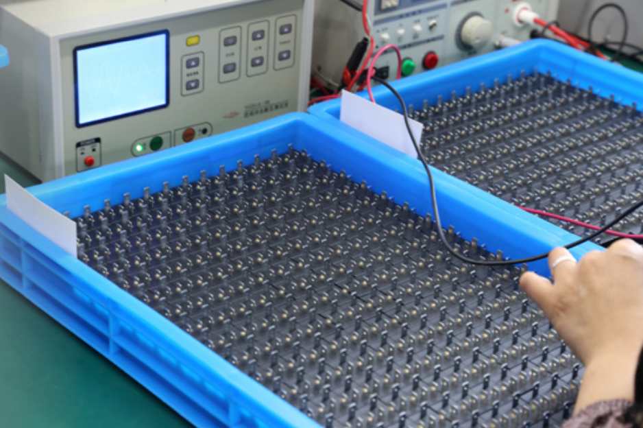
Step 1: Perform a Fit Check on the Actual Valve
The first check confirms that the coil installs without forcing, distortion, or unexpected interference.
I verify that the candidate coil:
- Slides onto the armature tube without excessive force
- Seats fully on the intended shoulder or locating surface
- Allows correct nut engagement and torque
- Does not crack or stress the encapsulation during assembly
- Clears nearby valves, brackets, tubing, and covers
- Allows the plug or flying leads to route correctly
- Preserves access to any manual override feature
Step 2: Check Electrical Characteristics at R20
I compare the candidate coil’s measured resistance, referenced to 20°C, with the approved drawing or engineering target. I also confirm voltage type, rated power or current, duty rating, and any polarity-sensitive components.
The test should not rely on a generic internet value for “24V coil resistance.” Coil resistance depends on the required magnetic force, coil volume, copper fill, duty cycle, power target, and valve design.
Step 3: Confirm Terminal Voltage and Polarity
I energize the valve through the actual PLC, driver, cable harness, and connector configuration where possible. This test captures the voltage the coil truly receives.
For a DC design with LED, diode, or TVS protection, I verify:
- Positive and negative terminal identification
- LED operation
- Driver compatibility
- Correct suppression behavior
- Absence of abnormal current draw
Step 4: Test Pull-In, Hold, and Release
I test valve behavior at the expected minimum operating voltage, not only at nominal supply voltage. I also test at representative pressure and temperature conditions.
The functional review should confirm:
- Reliable pull-in
- Stable holding
- Repeatable release
- No abnormal sound for DC operation
- Complete seating for AC operation
- No loss of manual override usability
Step 5: Conduct a Thermal Check
I recommend running the coil at rated duty, including 100% ED where required, at a representative ambient temperature. On valve islands, I also energize adjacent coils when that reflects normal or worst-case operation.
The thermal review should consider:
- Ambient temperature
- Valve-body temperature
- Adjacent coil heating
- Enclosure ventilation
- Insulation class
- Encapsulation condition after exposure
- Connector and cable temperature
Temperature limits and insulation classifications should be verified against the relevant product documentation and the actual application requirements. A qualified engineer should make the final application-specific judgment.
Step 6: Confirm Batch Consistency
For OEM approval, I test more than one sample. A single successful sample may hide variation in winding resistance, connector molding, lead length, or encapsulation.12
I recommend checking:
- Marking consistency
- R20 spread across samples
- Bore and height consistency
- Connector form and pin consistency
- Lead routing and strain-relief consistency
- Functional performance across samples
- Traceable lot identification
Pass / Redesign Decision Table
| Condition | Can be drop-in if | Must treat as redesign if |
|---|---|---|
| Same tube, same 24VDC, same DIN form | Geometry, R20, power, heat performance, and plug behavior all match | Any one of these requirements drifts |
| Voltage changes from 12V to 24V or 24V to 12V | Winding and valve performance are redesigned and revalidated | The old winding is reused without validation |
| Flying lead changes to DIN connector | Mechanical, wiring, sealing, polarity, and driver conditions are rechecked | Only the wire termination is changed |
| Lower wattage is requested | Hot-state pull-in force remains adequate | Magnetic force margin disappears |
| LED or diode is added | Polarity and PLC compatibility are confirmed | The plug is copied visually only |
| A failed coil is replaced | The root cause is understood and addressed | The new coil is copied from a burnt unknown part |
Example: A 24VDC Valve Island Replacement Review
Consider a pneumatic OEM with a 24VDC valve island. The current coil is rated around 3–4.8 W, operates at 100% ED, and uses a DIN connector. The cabinet ambient temperature reaches 40°C. At the last valve position, the PLC output and cable run provide only 21–22V at the coil terminals. The old coil shows heat discoloration.
The incorrect approach would be to buy another 24V coil with a similar hole and DIN-style appearance.
I would use this sequence instead:
- Photograph the old coil, connector face, lead exit, valve interface, and manifold spacing.
- Confirm that the original coil is 24VDC, not 24VAC.
- Measure terminal voltage at the coil while the real PLC output is energized.
- Measure bore, height, shoulder, nut interface, and outer envelope.
- Compare R20, rated power, duty cycle, insulation system, and connector form.
- Verify LED or diode polarity if the plug includes indication or suppression.
- Test hot-state pull-in on the real valve at the lowest expected terminal voltage.
- Run a thermal test with adjacent valves energized.
- Freeze the approved drawing, markings, electrical data, and inspection criteria for future batches.
At SolenElec, I would encourage an OEM to send the old coil, valve interface information, photographs, and real voltage condition for engineering review before freezing a replacement specification. That approach supports a controlled decision rather than an assumption based on appearance.
Frequently Asked Questions
Can I use any 24V coil as a solenoid coil replacement?
No. A 24V marking does not confirm voltage type, power, resistance, connector form, magnetic force, duty cycle, or polarity. I recommend confirming whether the coil is 24VAC or 24VDC and validating fit, hot-state pull-in, and thermal performance on the actual valve.
What is the most important measurement for a pneumatic solenoid coil replacement?
I do not rely on one measurement. Bore diameter is critical for installation, but height, shoulder location, nut interface, terminal voltage, R20 resistance, and connector details are also important. A coil can fit the armature tube and still fail electrically or thermally.
Can a lower-wattage solenoid coil replace a higher-wattage coil?
Possibly, but only after validation. A lower-wattage coil may reduce heat, yet it may also provide less magnetic force. I recommend testing pull-in and holding performance at the lowest expected terminal voltage and highest realistic operating temperature before approval.
Why should I measure voltage at the coil terminals?
Cable resistance, PLC output behavior, connectors, and long manifold wiring can reduce voltage between the power supply and the coil. Measuring at the terminals shows the voltage the coil actually receives, which directly affects pull-in force, heating, and reliability.
Does a DIN connector guarantee solenoid coil interchangeability?
No. DIN-style connectors can differ in form, pin spacing, earth contact, keying, cable exit, sealing, and integrated LED or suppression components. I verify the complete connector interface and its electrical behavior rather than relying on a similar visual shape.
Conclusion
A solenoid coil replacement should be called drop-in only after it passes mechanical, electrical, connector, magnetic, and thermal gates on the existing pneumatic valve. I do not treat a matching voltage stamp, tube diameter, or DIN appearance as sufficient proof. If any gate fails, the project needs a custom winding or a new interface, not hope that the next batch will be close enough. At SolenElec, we view drop-in approval as an engineering decision. Send the old coil, valve interface, photographs, and real terminal-voltage conditions before you freeze a replacement specification.
"Types, Uses and Processes of Solenoid Coils", https://www.iqsdirectory.com/articles/electric-coil/solenoid-coils.html. Engineering references on solenoid actuators describe coil suitability as a function of mechanical geometry, winding electrical characteristics, magnetic circuit behavior, and thermal limits, supporting the use of a multi-factor compatibility check rather than voltage marking alone. Evidence role: general_support; source type: research. Supports: A neutral engineering source should support that solenoid-coil compatibility depends on combined mechanical fit, electrical rating, magnetic performance, and thermal operating conditions.. Scope note: Such sources usually describe general solenoid design and qualification principles rather than this specific replacement checklist. ↩
"Solenoids and Electromagnets Glossary of Terms", https://www.solenoidcity.com/glossary.asp. Electromagnetic-actuator theory relates solenoid force to coil ampere-turns and magnetic-circuit geometry, which supports the concern that a lower-power replacement winding may not maintain pull-in force under low-voltage or hot-winding conditions. Evidence role: mechanism; source type: education. Supports: A source should explain that solenoid actuator force depends on coil current, number of turns, magnetic circuit geometry, and air gap, so reducing electrical power can reduce available pull-in margin.. Scope note: This supports the physical mechanism; the actual force margin for a particular pneumatic valve must still be verified by test. ↩
"Why Is My Solenoid Valve Coil Overheating? Causes and ...", https://www.solenoid-valve.world/solenoid-valve-coil-overheating. Solenoid-valve troubleshooting literature identifies coil overheating and burnout as potential outcomes of incorrect supply voltage, excessive duty, elevated ambient temperature, poor electrical connections, or failure of the armature to seat, supporting use of a burned coil as diagnostic evidence rather than a definitive master sample. Evidence role: general_support; source type: research. Supports: A source should support that solenoid-coil burnout may arise from electrical overstress, mechanical non-actuation, thermal environment, or duty-cycle misuse.. Scope note: Most troubleshooting sources give general failure mechanisms and do not determine the root cause in a specific failed coil without inspection. ↩
"Solenoid force calculations", https://www.eevblog.com/forum/beginners/solenoid-force-calculations/. Studies and design texts on solenoid actuators show that magnetic force is strongly dependent on air-gap length, supporting the concern that a coil seated too high on an armature tube can reduce pull-in margin. Evidence role: mechanism; source type: paper. Supports: A source should support that magnetic force in a solenoid actuator is strongly affected by air-gap length.. Scope note: The source supports the direction and mechanism of the effect; the magnitude for a given valve depends on the valve’s magnetic circuit. ↩
"AC vs DC Solenoid Coils: How to Choose the Right Voltage", https://valveman.com/blogs/the-valve-authority/ac-vs-dc-solenoid-coils-how-to-choose-the-right-voltage?srsltid=AU7gw4XjGMJfNrpEAb2URtBWLkg2FEBk0oh_s3egY958NlZcxHyC9M0X. Educational material on solenoid coils distinguishes AC-coil impedance and inrush behavior from DC-coil resistance-limited operation, supporting the statement that identical nominal voltage values do not make 24 VAC and 24 VDC coils interchangeable. Evidence role: mechanism; source type: education. Supports: A source should explain the electrical differences between AC and DC solenoid coils, including impedance, inductance, inrush behavior, and heating risk.. Scope note: This is general electrical support; some products may use rectifiers or dual-rated designs that require checking the manufacturer’s documentation. ↩
"How To Choose Solenoid Valve Voltage", https://tameson.com/pages/solenoid-valve-voltage. AC circuit theory shows that inductive reactance varies with frequency, and solenoid-coil guidance applies this principle to AC coils, supporting the need to verify 50 Hz and 60 Hz ratings separately when frequency is relevant. Evidence role: mechanism; source type: education. Supports: A source should support that AC-coil impedance and current depend on supply frequency, so operating frequency can influence temperature rise and magnetic performance.. Scope note: The source may establish the mechanism rather than quantify the performance change for a particular coil. ↩
"What Causes Solenoid Valve Coils To Burn Out?", https://clarkcooper.com/CCblog/?p=99. Technical guidance on electromagnetic coils defines duty cycle as a determinant of thermal loading and distinguishes intermittent from continuous operation, supporting the warning that an intermittent-duty coil can exceed its temperature limits at 100% energization. Evidence role: mechanism; source type: institution. Supports: A source should explain that coil temperature rise depends on energization time and thermal equilibrium, and that intermittent-duty coils may not be rated for continuous energization.. Scope note: The general duty-cycle principle does not replace the temperature-rise rating of the exact coil model. ↩
"A Selection Guide for DIN Valve (Solenoid) connectors", https://elcom-in.com/a-selection-guide-for-din-valve-solenoid-connectors-form-a-b-and-c-having-standard-din-en175301-803. DIN EN 175301-803 defines industrial rectangular connector interfaces in multiple forms and sizes, supporting the statement that a visually similar DIN-style solenoid plug is not automatically a universal or interchangeable interface. Evidence role: definition; source type: institution. Supports: A source should document that DIN EN 175301-803 defines multiple industrial connector forms with distinct dimensions and contact arrangements.. Scope note: The standard defines connector geometry; sealing and functional compatibility still depend on the complete plug, gasket, cable gland, and coil assembly. ↩
"How to Maintain an IP Rating When Modifying an Electrical ...", https://www.perancea.com/maintain-ip-rating-electrical-enclosure/. IEC 60529 defines ingress-protection ratings for enclosures under specified conditions, supporting the view that a coil’s practical IP performance depends on the assembled connector, seals, cable entry, and installation condition rather than the coil body alone. Evidence role: definition; source type: institution. Supports: A source should define IP ratings under IEC 60529 and support that ingress protection applies to an enclosure or assembly under specified test conditions.. Scope note: IEC 60529 provides the rating framework; it does not certify a specific solenoid-coil installation unless that assembly has been tested. ↩
"A method of adjusting the temperature coefficient and ...", https://nvlpubs.nist.gov/nistpubs/jres/12/jresv12n2p147_A2b.pdf. Reference data for copper electrical properties report a positive temperature coefficient of resistance near room temperature, supporting the use of temperature correction when comparing solenoid-coil winding resistance to an R20 specification. Evidence role: mechanism; source type: government. Supports: A source should support that copper has a positive temperature coefficient of resistance near room temperature and provide or contextualize the commonly used coefficient.. Scope note: The exact coefficient can vary with copper purity, temperature range, and the engineering standard used for the calculation. ↩
"Voltage Drop Issues", https://control.com/forums/threads/voltage-drop-issues.50393/. Basic circuit theory and industrial-control guidance describe voltage drop as the product of load current and series resistance in conductors and switching devices, supporting the practice of measuring solenoid-coil voltage at the terminals under load. Evidence role: mechanism; source type: education. Supports: A source should explain that load current through conductor, connector, and switching-device resistance causes voltage drop, so terminal voltage may be lower than supply voltage.. Scope note: The source establishes the mechanism; the actual voltage loss in a valve island depends on cable length, conductor size, connector condition, current, and PLC output design. ↩
"A Step-by-Step Process on Sample Size Determination ... - PMC", https://pmc.ncbi.nlm.nih.gov/articles/PMC8075593/. Quality-control standards for sampling inspection recognize that manufactured lots exhibit variation and use sample-based acceptance methods, supporting the article’s caution that one functioning coil does not by itself establish batch consistency. Evidence role: general_support; source type: institution. Supports: A source should support the quality-control principle that production lots can vary and that sampling plans are used to assess conformance beyond a single unit.. Scope note: Sampling standards support the quality principle but do not prescribe the exact test plan needed for a particular pneumatic-valve coil approval. ↩