In one OEM project, ambient temperature was overlooked because a solenoid coil operated normally during room-temperature testing. However, its pull-in performance dropped after the equipment warmed up. The voltage had not changed, and the coil had not failed. The original selection simply lacked enough allowance for the real installation temperature and coil self-heating.
Ambient temperature affects solenoid coil selection by changing winding resistance, current, magnetic force, heat dissipation, insulation aging, and service life.1 I recommend selecting a coil against its worst-case hot operating condition, including self-heating, duty cycle, valve-body heat, hot media, enclosure conditions, supply tolerance, and the required operating lifetime.
That case reflects a common selection gap. A room-temperature sample can pass an initial functional test but behave differently in a warm appliance, pneumatic system, or enclosed valve assembly. I therefore treat the stated room temperature as only one input, not as the complete thermal specification.
Why Does Ambient Temperature Matter When Selecting a Solenoid Coil?
Customers often provide a nominal voltage and a general ambient range, but those details may not describe what the installed coil experiences. If I select from incomplete information, the coil can overheat, lose hot-state force, or use expensive materials that do not solve the underlying problem.
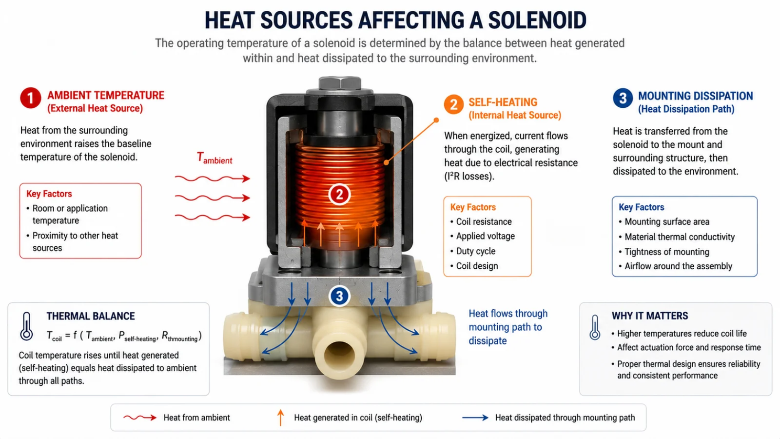
Ambient temperature matters because it establishes the starting point from which an energized coil heats itself. The actual winding temperature then depends on electrical power, energization time, airflow, enclosure design, valve-body temperature, hot media, and nearby components.2 Solenoid coil suitability must therefore be assessed under the complete thermal duty, not ambient temperature alone.
Stated ambient temperature is not always the real ambient temperature
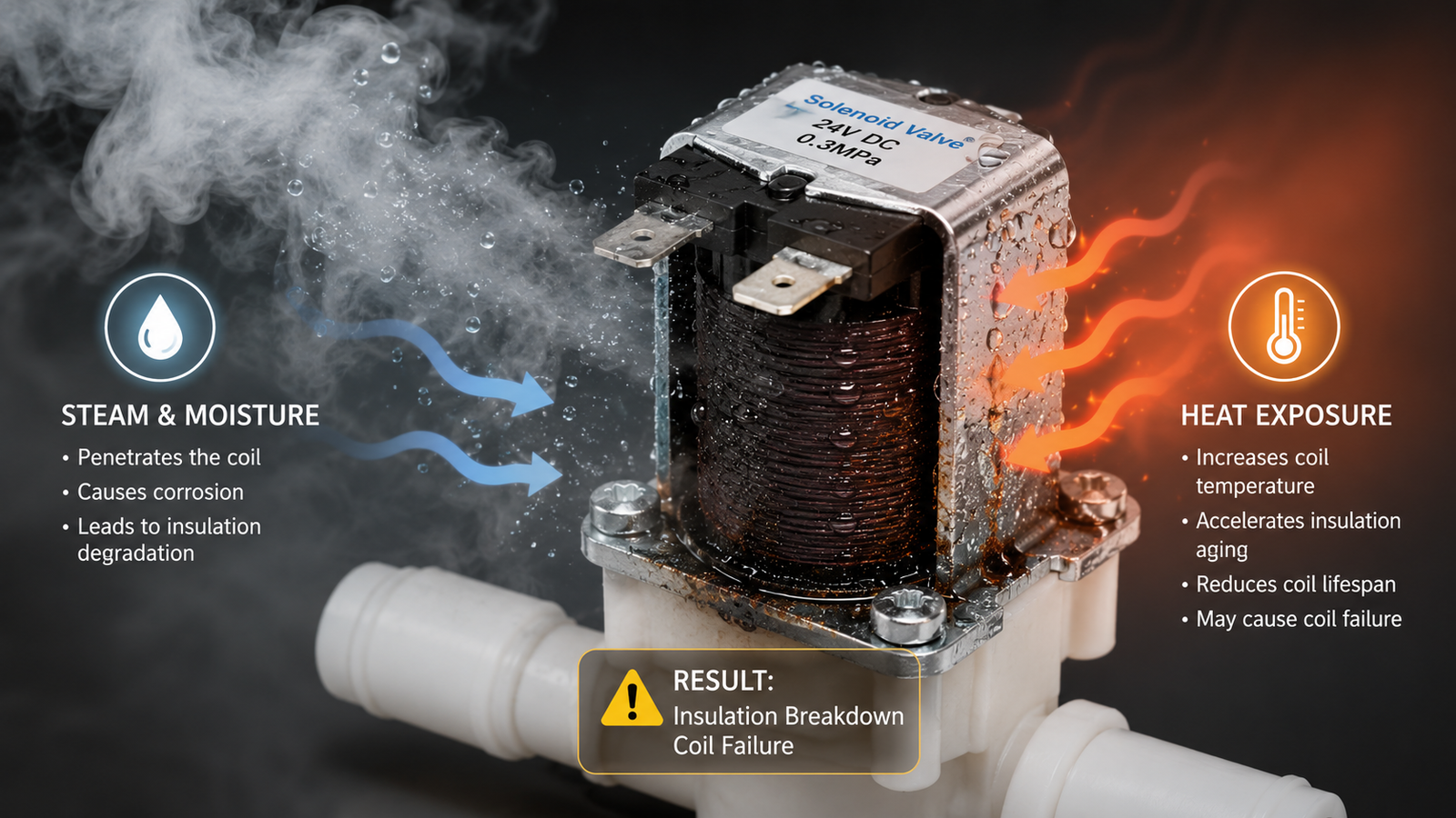
I first ask where and how the temperature was measured. A specification may describe the air outside the equipment, while the coil sits inside a closed cabinet beside a motor, compressor, heater, or power supply. The valve body may also conduct heat from steam, hot water, oil, or another process medium.
The coil can therefore receive heat from several directions:
- Self-heating from electrical losses in the winding
- Conducted heat from the valve body, armature tube, manifold, or mounting surface
- Radiated heat from heaters, burners, motors, or adjacent equipment
- Restricted convection inside a cover, cabinet, or molded assembly
- Hot process media flowing through the valve
- Thermal cycling during repeated equipment start-stop operation
I have seen project discussions change once we moved beyond the question, “What is the room temperature?” In one anonymized OEM case, the customer initially described a moderate operating environment. Further review showed that the coil was mounted in an enclosed area and received additional heat from nearby equipment and the valve body. We did not assume that the coil itself was the only cause. Instead, we redefined the installation conditions before reviewing the winding and material system.
That distinction changed the selection process. We considered energization behavior, enclosure conditions, external heat sources, and hot-state pull-in requirements rather than relying on room-temperature resistance and force.
Ambient temperature is only the thermal starting point
I use the following simplified concept during early discussions:
Final coil temperature is influenced by the starting ambient condition, coil self-heating, external heat input, and the installation’s ability to release heat.
This concept is not a substitute for measurement or thermal validation. However, it helps engineering and procurement teams avoid treating an ambient rating as a stand-alone guarantee.
A coil operating continuously in still air can face a very different thermal load from the same coil energized for a short pulse with a long cooling period. Likewise, an open-mounted valve and an enclosed valve may require different evaluations even when both products use the same voltage.
For that reason, I define the worst-case hot operating condition before recommending winding data, insulation, molding resin, or power level.
How Does Ambient Temperature Affect Coil Resistance, Current, and Magnetic Force?
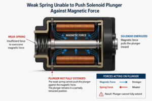
A coil may meet pull-in requirements during a room-temperature test and still become marginal after heat raises its winding resistance. If the design has little force margin, that change can cause delayed actuation, humming, incomplete armature travel, or inconsistent operation at low supply voltage.
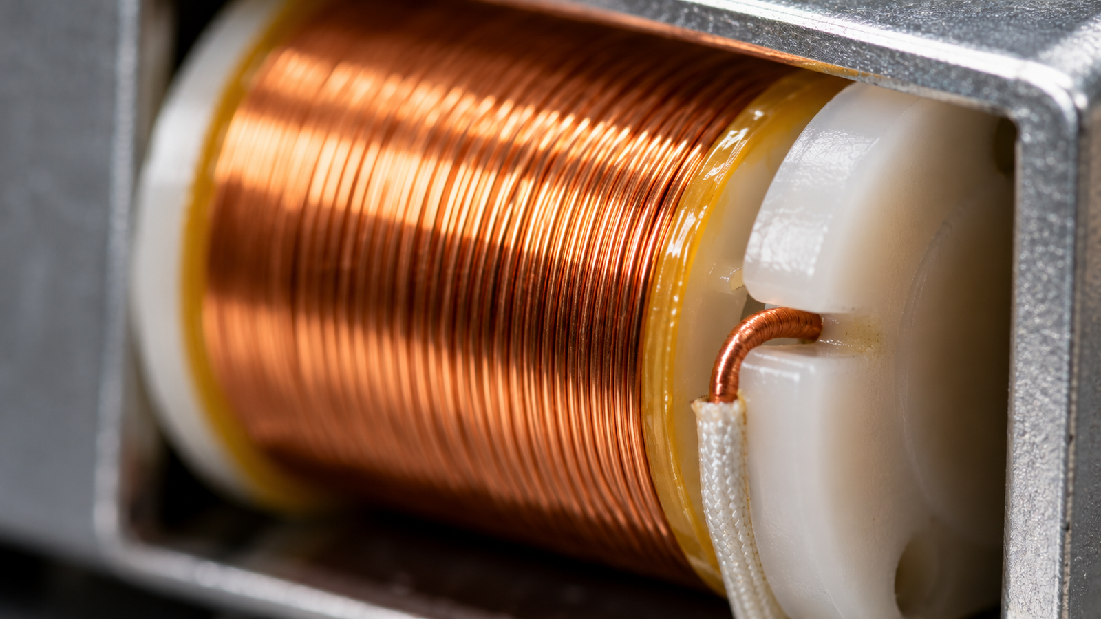
As ambient and winding temperatures rise, copper winding resistance increases. With a fixed DC supply voltage, higher resistance reduces current and ampere-turns, which can reduce available magnetic force. At the same time, self-heating changes because electrical power depends on voltage, current, resistance, control method, and operating state. Hot-state performance must therefore be validated directly.
Copper resistance rises with temperature
For an initial engineering estimate, I may use the standard linear resistance relationship:
[ R_T = R_0[1+alpha(T-T_0)] ]
In this expression:
- (R_T) is the winding resistance at the evaluated temperature.
- (R_0) is the resistance at a known reference temperature.
- (T) is the evaluated winding temperature.
- (T_0) is the reference temperature.
- (alpha) is the temperature coefficient of the conductor.
For copper near room temperature, engineers commonly use a coefficient of approximately 0.0039 per degree Celsius for preliminary calculations.3 The exact coefficient, reference condition, wire specification, and accepted test method should be verified for the project.
Under a constant DC voltage, Ohm’s law gives:
[ I = frac{V}{R} ]
As resistance rises, current falls.4 Since magnetomotive force depends on current and the number of turns, reduced current generally reduces available ampere-turns.5
However, I do not convert that relationship directly into a guaranteed percentage of force loss. Actual solenoid force also depends on:
- Air gap
- Armature position
- Magnetic circuit geometry
- Core and armature materials
- Flux saturation
- Spring or return-force requirements
- Friction and alignment
- Residual magnetism
- AC shading-ring or rectifier behavior, where applicable
Pull-in is usually more demanding than holding
I pay particular attention to hot pull-in performance. Once an armature has fully closed the working air gap, the solenoid may need less force to hold it in position.6 Pull-in starts with a larger air gap and often represents the more difficult condition.
A useful validation matrix includes both temperature and supply tolerance:
| Test condition | Why I evaluate it |
|---|---|
| Cold coil at nominal voltage | Confirms normal initial operation |
| Cold coil at maximum voltage | Checks current, power, and thermal stress |
| Hot coil at nominal voltage | Shows normal warmed-up behavior |
| Hot coil at minimum voltage | Checks worst-case pull-in margin |
| Maximum ambient with continuous duty | Evaluates thermal equilibrium risk |
| Repeated intermittent cycles | Evaluates heat accumulation and cycling |
| Hot valve body or process medium | Captures transferred external heat |
The exact matrix should follow the product’s operating profile and applicable standards.
Power behavior also depends on the supply method
For a simple fixed-voltage DC coil, electrical power can be expressed as:
[ P = VI = frac{V^2}{R} ]
As a copper winding becomes hotter and its resistance increases, current and power can decrease under a constant DC voltage.7 That fact does not mean higher ambient temperature is harmless. The coil is already starting from a hotter condition, heat rejection may be limited, and magnetic force may fall.
Other control systems behave differently. A constant-current driver, PWM controller, economizer circuit, rectified AC supply, or overexcitation-and-hold strategy can alter electrical and thermal behavior. I always ask how the coil is powered instead of assuming that the nameplate voltage describes the complete electrical condition.
How Should Ambient Temperature Be Matched with Coil Insulation Class?
Selecting a higher insulation class can appear to be an easy solution to solenoid coil overheating. However, that approach can increase cost without correcting inadequate magnetic force, excessive power, poor heat dissipation, incorrect duty, or hot valve-body conditions. The thermal class must match the whole design and application.
I match ambient temperature with insulation class by estimating or measuring the hottest winding condition, then checking the complete insulation system under the required duty and lifetime. A higher class indicates greater material-system thermal capability, but it does not guarantee a specific solenoid coil service life or compensate for every electrical and mechanical problem.
Insulation class applies to a system, not only one component
A solenoid coil contains more than magnet wire. Its thermal reliability can depend on the compatibility and processing of:
- Magnet-wire enamel
- Bobbin material
- Lead-wire insulation
- Terminals and joints
- Tapes, sleeves, and barriers
- Impregnation varnish or encapsulation compound
- Injection-molded housing
- Connectors and seals
- Manufacturing and curing processes
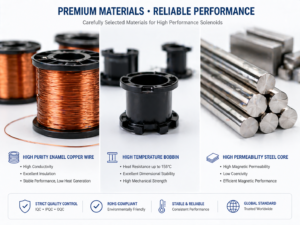
I therefore avoid describing a coil as suitable merely because one raw material carries a high-temperature rating. The insulation system must be evaluated as a combination.8
Common thermal-class reference values are often presented as follows:9
| Thermal class | Common reference temperature |
|---|---|
| Class A | 105°C |
| Class E | 120°C |
| Class B | 130°C |
| Class F | 155°C |
| Class H | 180°C |
These values are general reference classifications, not universal allowable coil operating temperatures. Project teams should verify current requirements under standards such as IEC 60085, relevant UL insulation-system requirements, product-specific standards, certification conditions, and the supplier’s validated construction.
Thermal class is not the same as service life
A higher insulation class does not tell me how long the finished coil will last in a specific valve or appliance. Actual life is affected by more than peak temperature.
Important variables include:
- The temperature at the winding hot spot
- The duration of exposure
- The number and severity of thermal cycles
- Voltage variation and transient conditions
- Moisture, chemicals, dust, and vibration
- Mechanical stress from molding and assembly
- Material compatibility
- Manufacturing consistency
- Armature movement and valve condition
- The customer’s required service life
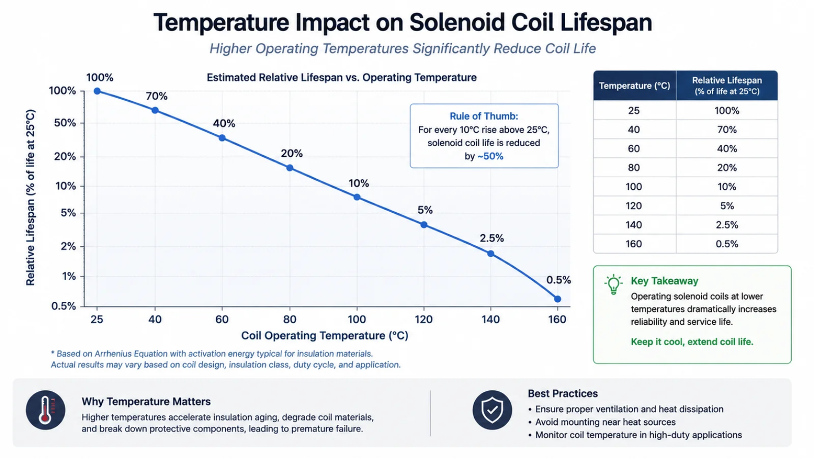
Thermal-aging models are sometimes used to estimate how temperature affects insulation life.10 I treat these models as engineering tools, not universal guarantees. The model, activation energy, material data, failure criteria, and actual duty must all be validated before anyone makes a lifetime claim.
Design margin should be application-specific
A procurement team may be tempted to request Class H for every warm application. That choice may be appropriate in some projects, but it can also create unnecessary cost. More importantly, it may distract the team from a hot-state magnetic-force problem.
For example, upgraded insulation may tolerate a higher winding temperature while the heated copper winding still draws less current at a fixed DC voltage. The material upgrade alone may therefore leave insufficient pull-in force unresolved.
I prefer to separate two questions:
- Can the insulation system tolerate the expected thermal duty?
- Can the solenoid still actuate reliably under the hottest, lowest-voltage condition?
A robust selection must answer both.
What Changes Are Needed for High-Temperature Solenoid Coil Applications?
High-temperature projects often begin with a request for “better wire” or “higher-temperature plastic.” That request can be too narrow. If the heat originates from continuous energization, a hot valve body, restricted airflow, or an unsuitable power strategy, changing one material may not provide a reliable solution.
High-temperature solenoid coil applications may require coordinated changes to winding design, power consumption, insulation materials, bobbin and encapsulation systems, lead wires, connectors, sealing, valve geometry, control strategy, and installation. I determine the changes only after defining the actual hot condition, required magnetic force, duty cycle, supply limits, environment, and target life.
Review the electrical design first
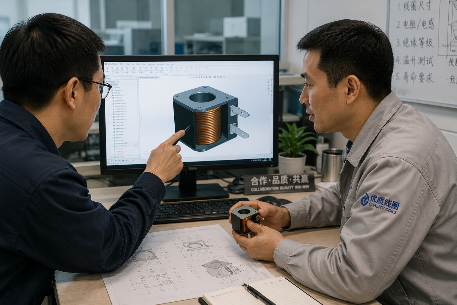
I begin by checking whether the winding is correctly matched to the supply and duty. The review may include:
- Wire diameter and conductor material
- Number of turns
- Cold and hot resistance
- Winding fill and winding consistency
- Nominal, minimum, and maximum voltage
- Continuous or intermittent energization
- Pull-in and holding current
- AC frequency or rectification method
- PWM frequency and duty ratio
- Overexcitation and reduced holding-power options
A lower-power holding strategy can sometimes reduce thermal load after actuation.11 However, the driver and solenoid must be engineered together. An excessively low holding current can allow the armature to release under vibration, pressure, or voltage variation.
Review the magnetic and mechanical system
A winding change affects more than temperature. If I increase resistance to reduce current, I must still confirm enough force across the operating air gap. I also review the armature, core, spring, pressure differential, stroke, friction, and alignment.
A coil can appear electrically overheated when the real problem begins mechanically. For example, an armature that does not close fully can leave an abnormal air gap. In some AC constructions, incomplete closure can contribute to excessive current and heating.12 Contamination, incorrect assembly, valve pressure, or damaged moving parts may also prevent full travel.
I therefore avoid attributing every high-temperature complaint to the winding.
Review every material exposed to heat
For a genuinely demanding thermal environment, the material review can cover:
| Component | Selection concern |
|---|---|
| Magnet wire | Enamel class, chemical resistance, winding process |
| Bobbin | Thermal capability, dielectric performance, dimensional stability |
| Encapsulation | Heat resistance, adhesion, cracking, moisture behavior |
| Lead wire | Conductor and insulation temperature capability |
| Connector | Contact stability, housing deformation, certification |
| Seal | Heat, fluid, and chemical compatibility |
| Terminal joint | Resistance, mechanical strength, process consistency |
| Valve interface | Conducted heat and dimensional fit |
I verify the complete bill of materials rather than approving a coil from the magnet-wire specification alone.
Improve thermal management where practical
The product team may also reduce the coil’s thermal burden by changing the installation. Possible measures include:
- Increasing airflow around the coil
- Moving it away from a heat source
- Adding a thermal barrier where technically appropriate
- Reducing heat conduction from adjacent components
- Increasing spacing inside the enclosure
- Using an economizer or controlled holding current
- Reducing unnecessary energized time
- Reviewing the valve body and manifold thermal path
Each measure has trade-offs. For example, a thermal barrier may reduce external heat transfer but can also restrict the coil’s own heat dissipation. I rely on prototype testing under representative conditions before approving the final approach.
What Ambient Temperature Checklist Should Guide Solenoid Coil Selection?
Incomplete input data creates avoidable risk. Engineering may test a bare valve in open laboratory air, while production installs it inside a compact appliance. Procurement may then compare quotations for coils that were designed against different assumptions. A standard checklist keeps technical and commercial comparisons aligned.
An ambient temperature checklist for solenoid coil selection should document the real coil-location temperature, external heat sources, enclosure, airflow, media temperature, duty cycle, supply limits, hot-state force requirement, insulation system, environmental exposure, target lifetime, and validation method. I use the worst credible combination of these inputs as the design condition.

Step 1: Define the installed thermal environment
I ask the customer to provide:
- Minimum and maximum air temperature at the coil location
- Measurement location and method
- Valve-body or manifold temperature
- Process-media type and temperature
- Nearby heat-generating components
- Distance from heaters, motors, or compressors
- Enclosure dimensions and ventilation
- Airflow during normal operation
- Start-up, steady-state, and shutdown conditions
- Abnormal but credible operating conditions
Photographs, assembly drawings, thermal images, and temperature logs can be more useful than a single maximum-ambient number.
Step 2: Define the electrical duty
I then document:
- Supply type: AC, DC, rectified AC, PWM, or controlled current
- Nominal voltage
- Minimum and maximum operating voltage
- Frequency, where relevant
- Voltage ripple and tolerance
- Continuous or intermittent duty
- Energized and de-energized times
- Maximum cycles per operating period
- Pull-in pulse and holding strategy
- Simultaneous operation of nearby coils
The duty statement should describe the real equipment logic. Terms such as “intermittent” are not sufficient unless the on-time, off-time, cycle pattern, and worst-case repetition are defined.
Step 3: Define the required output
A coil should not merely survive. It must operate the valve correctly. I confirm:
- Required stroke
- Initial and final air gaps
- Spring force
- Pressure differential
- Required pull-in force
- Required holding force
- Release requirements
- Response-time target
- Hot and cold operating limits
- Acceptable noise or vibration
I place special emphasis on pull-in at the hottest coil condition and minimum allowed voltage. This combination often reveals a margin that room-temperature testing misses.
Step 4: Define life and compliance expectations
The customer should also specify:
- Required product life or cycle target
- Expected operating hours
- Thermal-cycle profile
- Moisture and ingress conditions
- Chemical or cleaning-agent exposure
- Vibration and shock
- Required CE, UL, RoHS, REACH, TUV, IEC, or product-specific compliance
- Traceability and change-control requirements
- Sampling, inspection, and qualification plans
Compliance marks do not replace application validation. I check which standards apply to the finished equipment, which apply to the component, and which test conditions are covered by the existing certification.
Step 5: Validate the worst-case combination
I recommend a documented decision sequence:
- Measure or estimate the coil-location environment.
- Add the effect of external heat paths and self-heating.
- Calculate preliminary cold and hot electrical behavior.
- Check magnetic force across voltage and temperature limits.
- Select a compatible insulation and material system.
- Build representative samples.
- Test inside or alongside the actual assembly.
- Review hot spots, pull-in, holding, release, and cycling.
- Confirm manufacturing tolerances and quality controls.
- Freeze the specification with traceable acceptance criteria.
At SolenElec, we support this process with OEM/ODM design, prototyping, coil winding, injection molding, material selection, and production validation. Our MES-supported traceability and outgoing inspection help control production consistency, but the initial application definition remains essential. A stable factory process cannot correct an incomplete thermal requirement.
Frequently Asked Questions
Can I select a solenoid coil from the maximum ambient temperature alone?
No. I also need the coil’s self-heating, duty cycle, supply range, valve-body temperature, process-media temperature, airflow, enclosure, external heat sources, magnetic-force requirement, and target lifetime. The maximum air temperature is only one part of the total thermal duty.
Does a higher insulation class guarantee a longer solenoid coil service life?
No. A higher class indicates the thermal capability of a qualified insulation material system under defined conditions. It does not guarantee service life in a specific installation. Winding temperature, thermal cycling, voltage, moisture, chemicals, mechanical stress, manufacturing quality, and duty all affect reliability.
Why can a coil pass at room temperature but fail to pull in when hot?
Copper resistance rises as the winding heats. Under a fixed DC voltage, the increased resistance reduces current and available ampere-turns. If the initial force margin is small, the hot coil may not overcome the spring, pressure load, friction, and working air gap.
Should I test the coil separately or in the complete valve assembly?
I recommend both, but the complete assembly provides the more representative thermal result. The valve body, hot media, mounting method, enclosure, airflow, and nearby components can change the temperature substantially. Final validation should reproduce the real installation and operating cycle as closely as practical.
Can reducing coil power solve every overheating problem?
No. Lower power may reduce self-heating, but it can also reduce pull-in or holding force. It will not automatically correct external heat, excessive voltage, mechanical sticking, an abnormal air gap, poor airflow, or an incompatible material system. I evaluate the electrical, magnetic, mechanical, and thermal system together.
Conclusion
Ambient temperature should never be treated as a stand-alone number during solenoid coil selection. I base the decision on the worst-case hot operating condition, including self-heating, duty cycle, voltage tolerance, hot media, valve-body heat, enclosure, airflow, magnetic-force margin, insulation system, and required life. This approach helps prevent room-temperature samples from becoming production-stage thermal problems while avoiding unnecessary material over-specification.
If you need an OEM or ODM coil evaluated for a home-appliance, pneumatic, automotive, or solenoid-valve application, contact SolenElec with your installation and duty details. Our engineering team can help translate them into a practical coil specification and validation plan.
"Inductor", https://en.wikipedia.org/wiki/Inductor. A neutral electromagnetic-device or insulation-aging reference supports the mechanism that elevated coil temperature changes winding resistance and current, which can alter electromagnetic output, while also accelerating thermal stress on insulation systems; the source would provide general engineering support rather than proof of any specific solenoid model's lifetime. Evidence role: mechanism; source type: research. Supports: The source should explain how coil temperature affects conductor resistance, current, electromagnetic force, heat transfer, and insulation degradation.. Scope note: Contextual support; the exact magnitude depends on the coil geometry, materials, duty cycle, and installation. ↩
"25 Thermal Modeling and Heat Sinking", https://circuits.mit.edu/_static/F23/6s060/KPVS_ThermalModeling.pdf. Heat-transfer and electrical-machine thermal references describe winding temperature as the result of internal loss generation balanced against conduction, convection, radiation, and surrounding boundary conditions; this supports the article's thermal framing but does not validate the listed conditions for every valve installation. Evidence role: mechanism; source type: education. Supports: The source should support that winding temperature is determined by heat generated electrically and by the ability of the surrounding structure and air to remove or add heat.. Scope note: Contextual support; installation-specific measurements are still required. ↩
"Grain boundary strengthening", https://en.wikipedia.org/wiki/Grain_boundary_strengthening. A materials-property reference gives copper's temperature coefficient of electrical resistance near room temperature as about 0.0039 K−1, supporting its use for preliminary winding-resistance estimates; the value is approximate and depends on purity, reference temperature, and measurement conditions. Evidence role: statistic; source type: government. Supports: The source should provide a recognized value for copper's temperature coefficient of electrical resistance near room temperature.. Scope note: The coefficient is an approximation, not a substitute for project-specific wire data. ↩
"Ohm's law - Simple English Wikipedia, the free encyclopedia", https://simple.wikipedia.org/wiki/Ohm%27s_law. Introductory circuit references state Ohm's law as I = V/R, which directly supports the statement that, under a fixed voltage, current decreases as resistance increases; this is a circuit-level relationship and does not by itself quantify solenoid force. Evidence role: definition; source type: education. Supports: The source should define Ohm's law and show the inverse relationship between current and resistance at constant voltage.. Scope note: Direct support for the electrical relationship only, not for complete solenoid performance. ↩
"Ampere-turn", https://en.wikipedia.org/wiki/Ampere-turn. Electromagnetics texts define magnetomotive force for a coil as proportional to N·I, supporting the article's statement that reduced current lowers ampere-turns; the source supports the magnetic-drive mechanism, while actual solenoid force still depends on magnetic-circuit geometry and air gap. Evidence role: mechanism; source type: education. Supports: The source should explain magnetomotive force as the product of current and number of turns in a coil.. Scope note: Contextual support; ampere-turns are not a complete force calculation. ↩
"Solenoid (engineering)", https://en.wikipedia.org/wiki/Solenoid_(engineering). Electromagnetic-actuator references describe solenoid force as strongly dependent on air gap, with force increasing as the magnetic gap closes, supporting the distinction between pull-in and holding conditions; this is general actuator behavior and may vary with the specific spring, pressure, and magnetic circuit. Evidence role: mechanism; source type: education. Supports: The source should explain the relationship between solenoid air gap and magnetic force, including why a closed or smaller gap can require less holding effort.. Scope note: Contextual support; individual solenoid designs require testing. ↩
"Temperature Coefficient of Resistance", http://hyperphysics.phy-astr.gsu.edu/hbase/electric/restmp.html. Basic circuit theory and conductor-property references together support that a hotter copper winding has higher resistance and, under a fixed DC voltage, lower current and lower P = V²/R power; this does not imply thermal safety because heat rejection and magnetic force may still be inadequate. Evidence role: mechanism; source type: education. Supports: The source should support that copper resistance rises with temperature and that, for fixed voltage, current and power follow I = V/R and P = V²/R.. Scope note: Direct support for simple DC operation only; controlled-current, PWM, and AC systems may behave differently. ↩
"CEI60085 1985 Electrical Insulation Thermal evaluation and designation", https://www.academia.edu/35420436/CEI60085_1985_Electrical_Insulation_Thermal_evaluation_and_designation. Electrical-insulation-system standards describe insulation performance as a property of an evaluated combination of materials and construction, supporting the article's statement that one high-temperature component does not establish the rating of the complete coil system; the citation provides standards context rather than a qualification of any named construction. Evidence role: expert_consensus; source type: institution. Supports: The source should support that electrical insulation ratings are assigned to evaluated systems of compatible materials and processes, not merely to individual components.. Scope note: Contextual support; a specific coil requires its own evaluated construction or certification basis. ↩
"Insulation system", https://en.wikipedia.org/wiki/Insulation_system. Standards-based insulation references identify thermal classes such as A, E, B, F, and H with commonly cited temperature indices including 105°C, 120°C, 130°C, 155°C, and 180°C; these are classification references and not universal permissible operating temperatures for a finished coil. Evidence role: definition; source type: institution. Supports: The source should identify standard insulation thermal classes and their associated reference temperatures.. Scope note: The class values do not replace product-specific certification or thermal validation. ↩
"Electrolytic capacitor", https://en.wikipedia.org/wiki/Electrolytic_capacitor. Thermal-endurance literature for electrical insulating materials commonly uses Arrhenius-type models to relate elevated temperature exposure to insulation aging and estimated life; such models support the article's claim but require validated material data, failure criteria, and duty profiles for a specific lifetime estimate. Evidence role: mechanism; source type: paper. Supports: The source should explain thermal aging or thermal endurance models for electrical insulation and their dependence on temperature.. Scope note: Contextual support; models do not provide a universal service-life guarantee. ↩
"Contactor", https://en.wikipedia.org/wiki/Contactor. Studies and application-neutral references on peak-and-hold solenoid control show that reducing current after pull-in lowers average electrical power dissipation and can reduce coil heating; this supports the general mechanism but does not determine the minimum safe holding current for a particular valve. Evidence role: mechanism; source type: paper. Supports: The source should support that peak-and-hold or economizer control can reduce average power dissipation and coil heating after actuation.. Scope note: Contextual support; holding-force margin must be verified for the specific application. ↩
"Air conditioning", https://en.wikipedia.org/wiki/Air_conditioning. Technical references on AC solenoids describe high inrush current associated with an open magnetic gap and reduced current after armature closure, supporting the statement that incomplete closure can contribute to overheating in some AC constructions; the mechanism is not necessarily applicable to DC or electronically controlled coils. Evidence role: mechanism; source type: research. Supports: The source should explain that AC solenoid current can remain high when the armature does not close and the magnetic circuit retains a large air gap.. Scope note: Applies primarily to relevant AC solenoid designs. ↩