How Ambient Temperature Affects Solenoid Coil Performance and Selection
Ambient temperature solenoid coil selection becomes difficult when a coil performs well on a bench but fails after installation in a hot, enclosed, or cold machine environment. I have seen buyers focus on room-temperature tests, only to discover weak pull-in, excess heat, or slow valve response later. The solution is to evaluate the complete installed thermal condition.
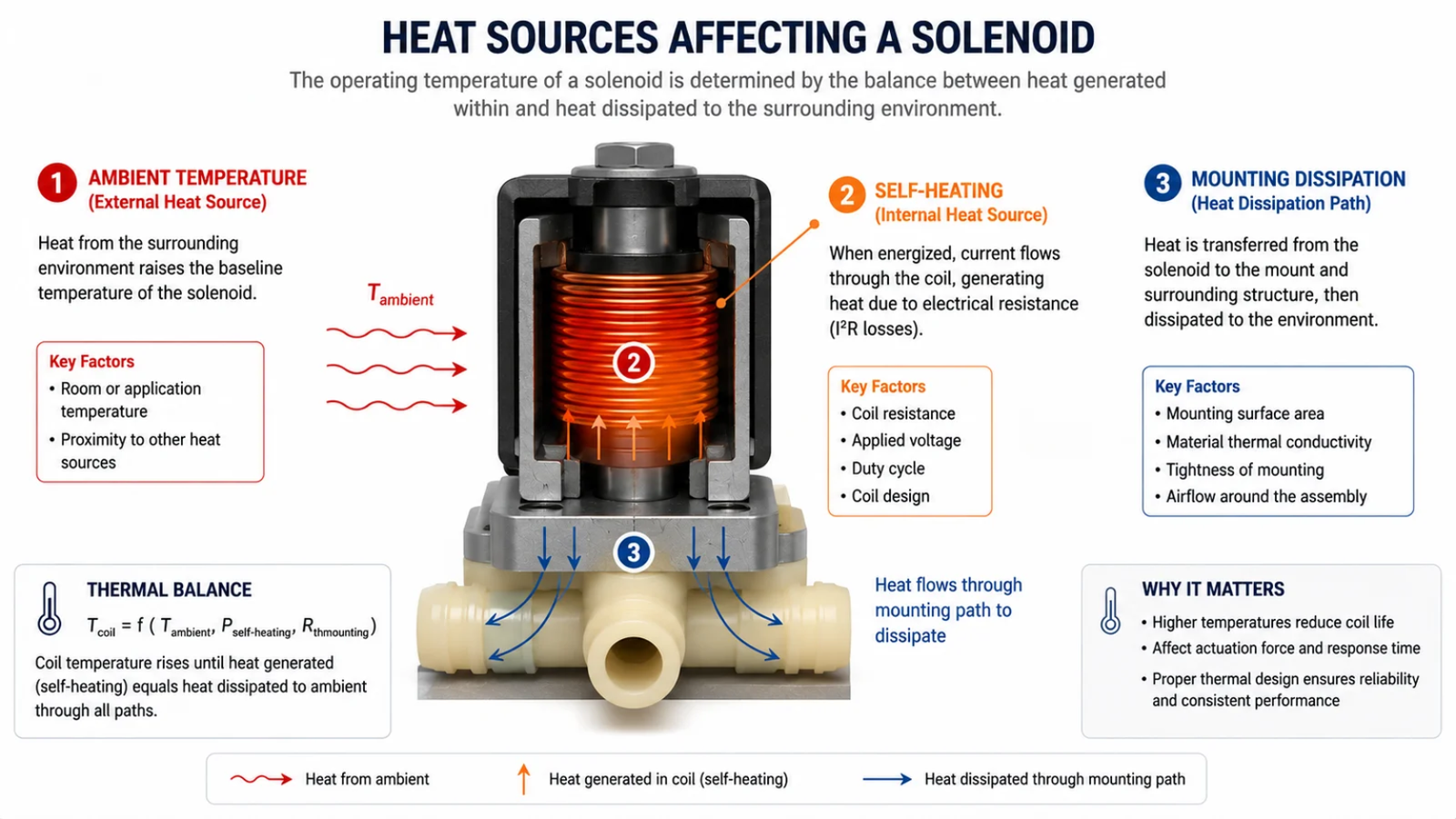
Ambient temperature affects a solenoid coil by changing its starting thermal condition, cooling capacity, electrical resistance, current, and magnetic operating margin.1 However, ambient temperature alone does not define solenoid coil temperature. Engineers should combine local ambient heat, coil self-heating, valve-body and media heat, enclosure conditions, airflow, duty cycle, and voltage tolerance, then validate operation at the hottest condition and minimum allowed voltage.
I recommend treating temperature as a system-level design input rather than a single rating on a purchase specification. A reliable coil must survive its real thermal exposure and still generate enough force to actuate the valve or mechanism under the most demanding operating condition.
Why Does Ambient Temperature Matter for a Solenoid Coil?
An ambient temperature solenoid coil can appear correctly selected when the buyer only compares a stated ambient range with a wire insulation class. That approach creates risk because the surrounding air temperature may not match the temperature at the installed coil location. The real machine environment is often much harsher than the datasheet assumption.
Ambient temperature matters because it affects how much heat a solenoid coil can reject and how hot the coil becomes in service. The installed coil temperature results from environmental heat, coil self-heating, heat transferred from the valve body or media, and the amount of heat the assembly can dissipate through airflow, mounting, and surrounding materials.2
Ambient Temperature Is Not Coil Operating Temperature
I use a simple thermal-balance concept during early project discussions:
Installed coil temperature = environmental heat + internally generated heat − heat dissipated by the assembly
This is not a precise mathematical formula. It is a practical way to prevent a common sourcing mistake: assuming that a coil installed near 25°C air will operate at 25°C.
The coil temperature depends on several interacting heat sources and cooling paths:
- Ambient air temperature near the coil
- Copper-loss heating from current through the winding
- Valve-body temperature
- Media temperature, especially with steam, hot water, oil, or compressed air
- Nearby equipment, such as compressors, boilers, motors, heaters, or power electronics
- Enclosure design, including cabinet size and ventilation
- Airflow around the coil
- Mounting materials that may conduct or retain heat
- Duty cycle, including continuous energization and pulse frequency
Ask Where “Ambient” Was Measured
A buyer may specify an ambient temperature of 40°C. I would ask a second question immediately:
Where was the ambient temperature measured?
The answer can change the coil design requirement. For example, a 40°C room may contain a machine enclosure operating at 60°C or higher3. A valve manifold near a coffee-machine boiler, compressor compartment, or steam line may experience local heat well above the general room condition.
| Measurement Location | What It May Represent | Selection Risk |
|---|---|---|
| Factory room air | General building temperature | May ignore machine heat |
| Outside cabinet | External environment | May ignore enclosure heat buildup |
| Inside control enclosure | Local cabinet temperature | May still miss valve-body heat |
| Near coil mounting location | More realistic local ambient | Better starting point |
| Coil surface | External coil temperature | Does not equal winding hot-spot temperature |
A coil surface measurement is useful, but I do not treat it as the same as winding hot-spot temperature.4 The internal winding can be hotter than the measured surface, depending on coil construction, encapsulation, heat path, and operating state.
For OEM procurement, I recommend that the buyer document the minimum and maximum temperature at the actual coil location, not only the general machine ambient. This creates a stronger basis for supplier comparison and validation planning.
How Does Ambient Temperature Affect Solenoid Coil Resistance, Current, and Magnetic Force?
Temperature changes can create an invisible magnetic-margin problem. A solenoid may pull in normally when cold at nominal voltage, then become unreliable after the machine reaches thermal equilibrium. This issue is especially important where a valve must actuate against pressure, spring force, friction, or a meaningful initial air gap.
For a fixed-voltage DC solenoid coil, higher copper temperature generally increases winding resistance and reduces current. Lower current can reduce ampere-turns and magnetic margin. A hot coil may therefore have less pull-in capability than a cold coil, especially at minimum supply voltage and maximum mechanical load.
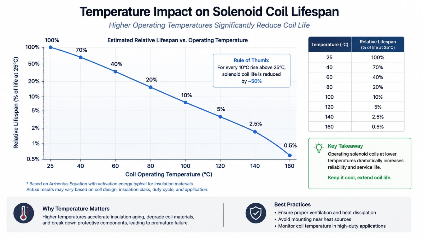
DC Coils: Heat Changes the Electrical Starting Point
Copper resistance rises as temperature rises.5 In a conventional fixed-voltage DC design, this generally leads to the following chain:
- Copper temperature increases
- Winding resistance increases
- Current generally decreases
- Ampere-turns decrease
- Magnetic margin may decrease
I use the word “may” deliberately. Solenoid force is not controlled by current alone. The actual result depends on the magnetic circuit and application load.
Magnetic force can also depend on:
- Air gap and stroke position
- Pole geometry
- Magnetic material
- Saturation level
- Return spring force
- Pressure differential across the valve
- Plunger alignment
- Friction and contamination
- Seal drag
- Valve-body tolerance
Therefore, I do not recommend claims such as “a 20°C rise causes a fixed percentage of force loss.” That statement would oversimplify a system that must be tested in its installed configuration.
Why Hot Pull-In Is Usually the Critical Condition
Pull-in usually requires more force than holding because the armature starts with a larger air gap.6 Once the armature is seated, the magnetic circuit is more complete and the holding requirement may be lower.
This is why I consider the following validation point especially valuable:
Hot coil + minimum supply voltage + maximum mechanical load
A coil can hold reliably after pull-in but still fail to pull in under hot conditions. This distinction matters for appliance valves, pneumatic systems, fluid-control assemblies, and automated mechanisms that must start from a fully open or unseated position.
AC Coils Require Different Analysis
I do not apply the simple DC relationship of voltage divided by resistance directly to AC coils. AC solenoid behavior also depends on:
- Inductance
- Frequency
- Impedance
- Air gap
- Armature seating condition
- Shading-ring or equivalent AC design features
In a conventional AC solenoid, an armature that does not fully close can cause abnormal current and overheating.7 The coil may hum, run excessively hot, or fail prematurely because the intended magnetic circuit is not achieved.
For this reason, I recommend reviewing both coil performance and the mechanical reasons for incomplete armature seating. Buyers can also review our guide on common solenoid coil burnout causes when investigating overheating or field-return patterns.
What Happens to an Ambient Temperature Solenoid Coil at High and Low Temperatures?
Many selection guides treat high temperature as the only concern. High heat is important, but low temperature can also create serious valve-level and mechanical risks. A coil may cool more effectively in cold air while the valve becomes harder to actuate because the media, seals, moisture, or mechanical tolerances have changed.
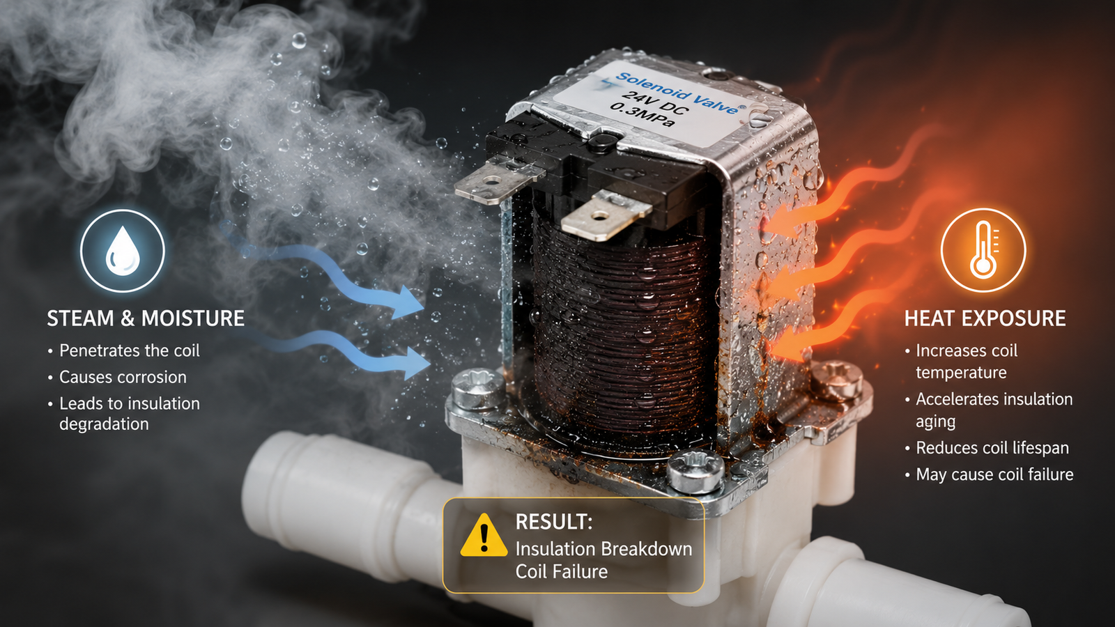
High ambient temperature reduces cooling margin and can increase coil temperature, resistance, and material aging.8 Low ambient temperature can reduce coil resistance but may increase fluid viscosity, seal stiffness, ice formation, and mechanical resistance. Both conditions should be evaluated as complete solenoid-system operating states.
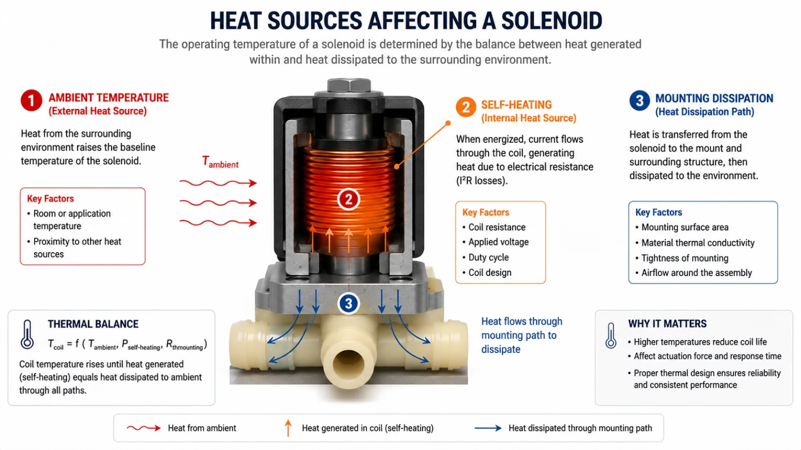
High Ambient Temperature: Less Margin for Self-Heating
High ambient temperature does not automatically cause failure. However, it gives the coil less thermal margin before self-heating begins. A coil installed in a 60°C cabinet starts from a much higher temperature than the same coil installed in a ventilated 25°C area.
High temperature can contribute to:
- Higher winding resistance in fixed-voltage DC coils
- Reduced hot pull-in margin
- Faster aging of magnet-wire insulation
- Stress on bobbins, encapsulation compounds, lead wires, terminals, and connectors
- Greater risk from nearby hot media or valve-body heat
- Reduced long-term reliability if the completed material system is not suitable
High temperature also affects the valve, not only the coil. For example, heat can change seal hardness, lubricant behavior, plastic dimensions, and fluid properties. These changes may increase the mechanical force required to actuate the valve.
Low Ambient Temperature: Better Cooling Does Not Always Mean Easier Actuation
I avoid saying that low temperature is always beneficial. Cold conditions can reduce copper resistance, which may increase current in a simple fixed-voltage DC coil. Yet the actual thermal result still depends on coil design, voltage, duty cycle, mounting, and heat dissipation.
More importantly, low temperature may make the valve mechanically harder to operate:
- Fluid viscosity can increase9, especially in hydraulic oils and process fluids.
- Elastomer seals can stiffen, creating more friction or slower response.
- Condensation can freeze, obstructing plunger or valve movement.
- Materials can contract, changing clearance, seal fit, and mechanical tolerance.
- Lubricants can thicken, increasing friction in moving components.
Low ambient temperature can improve coil cooling while making the valve mechanically harder to actuate.
This is a useful principle for buyers of low-temperature solenoid valves, refrigeration components, outdoor equipment, and industrial fluid-control systems. The coil must still provide adequate pull-in force against the changed mechanical load.
Temperature Effects: A Practical Comparison
| Condition | Primary Coil Effect | Primary Valve/System Effect | Key Validation Focus |
|---|---|---|---|
| High ambient | Less cooling margin; hotter winding | Hot seals, media, and valve body may alter load | Hot pull-in and steady-state temperature |
| Low ambient | Lower winding resistance may change current | Viscous media, stiff seals, frozen moisture | Cold actuation and mechanical response |
| Hot media | External heat enters coil assembly | Fluid and seal properties may change | Installed coil temperature and pull-in |
| Enclosed cabinet | Heat accumulates around coil | Local ambient differs from room air | Thermal equilibrium under full machine load |
| Repeated cycling | Heat may accumulate over time | Dynamic response may vary | Cycling test at realistic duty |
Does a Higher Insulation Class Solve Ambient Temperature Solenoid Coil Problems?
A higher insulation class can be valuable, but it is not a universal answer to high-temperature applications. I have seen specifications focus on “Class H” before confirming whether the coil can still actuate at hot conditions. Material survival and magnetic performance are related, but they are not the same engineering question.
A higher insulation class does not automatically solve ambient temperature solenoid coil problems. Insulation class concerns thermal capability of the insulation system, while reliable operation also requires sufficient hot-state magnetic force, suitable non-wire materials, acceptable voltage conditions, and validation of the complete installed solenoid assembly.
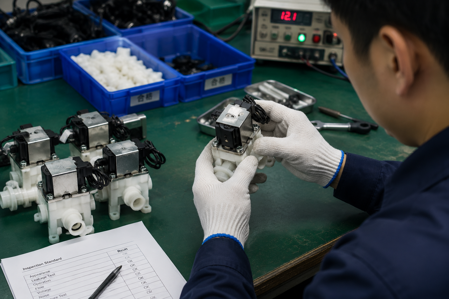
The Finished Coil Is a Complete Material System
A solenoid coil is not only magnet wire. A reliable high-temperature design must consider every temperature-sensitive part, including:
- Magnet-wire enamel
- Bobbin material
- Encapsulation resin or overmolding material
- Varnish or adhesive
- Lead wire insulation
- Terminals
- Connector housing
- Seals and adjacent valve materials
- Manufacturing process controls
The finished coil’s thermal capability is limited by the complete insulation and material system, not by the magnet-wire rating alone.
A basic insulation-class reference may include Class B, Class F, and Class H. However, I do not treat these classes as direct operating-temperature permissions for an assembled coil.
A thermal class reference is not the same as allowable coil surface temperature, winding hot-spot temperature, or guaranteed service life.10
Buyers should request and verify the supplier’s relevant technical documents for the specific coil construction, materials, and application conditions. Compliance claims, test reports, and certifications should always be reviewed against the actual project requirement rather than assumed to cover every installation scenario.
Higher Thermal Class Does Not Create More Magnetic Force
This is the key distinction:
- Can the materials survive the temperature?
- Can the solenoid still actuate reliably at that temperature?
A higher-temperature wire system may improve material durability. However, it does not automatically restore current or magnetic force lost because a fixed-voltage DC winding becomes more resistive when hot.
For example, if a coil has inadequate hot pull-in margin, changing only to a more heat-resistant wire may allow the coil to tolerate higher winding temperature. It may not provide the additional ampere-turns required to move the plunger under pressure.
Potential solutions may involve coil design, winding parameters, magnetic-circuit design, power-management strategy, valve mechanics, or application duty. Each option requires qualified engineering evaluation. I recommend reading our overview of solenoid coil design considerations when comparing these design trade-offs.
How Should Engineers Select and Validate an Ambient Temperature Solenoid Coil?
The strongest selection process starts with the actual installation rather than a generic coil rating. Buyers should define the thermal, electrical, and mechanical conditions before requesting a quote. Then they should validate the complete valve-and-coil assembly under the conditions that create the lowest operating margin.
Engineers should select an ambient temperature solenoid coil by defining the real coil-location temperature, electrical duty, magnetic load, complete material system, and installed validation plan. The most valuable test condition is often hot coil, minimum allowed voltage, and maximum expected mechanical load.
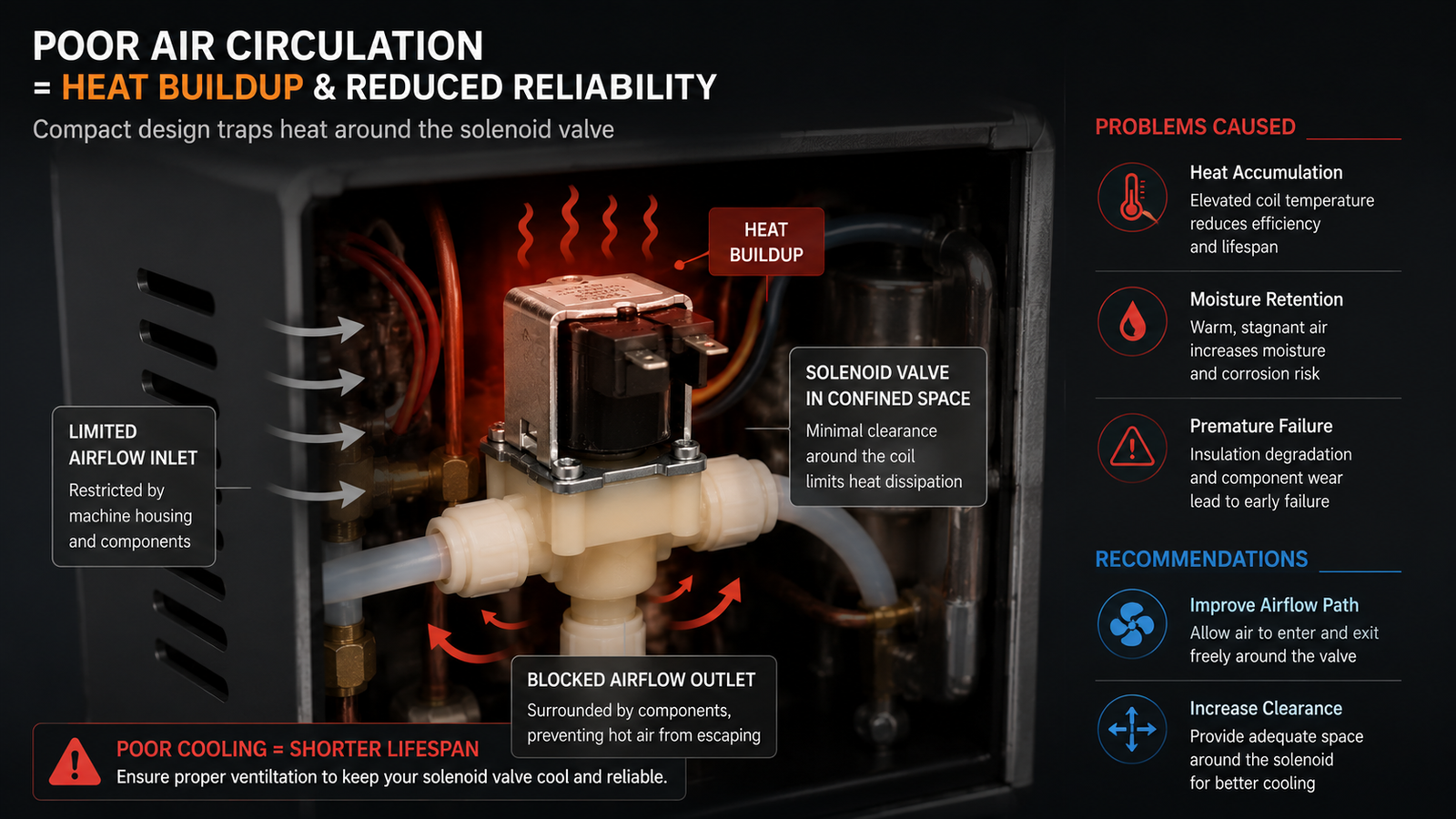
Step 1: Define the Real Temperature Range
I recommend documenting more than “ambient: -20°C to 80°C.” The engineering brief should identify:
- Minimum and maximum coil-location temperature
- Temperature inside the enclosure
- Valve-body temperature
- Media temperature
- Nearby heat sources
- Airflow and ventilation condition
- Start-up temperature versus steady-state temperature
- Orientation and mounting arrangement
This information helps suppliers evaluate whether the coil is exposed mainly to self-heating, external heat transfer, poor ventilation, or a combination of all three.
Step 2: Define the Electrical Duty
The electrical specification should include:
- AC or DC supply
- Nominal voltage
- Minimum allowed voltage
- Maximum allowed voltage
- Frequency for AC coils
- Continuous or intermittent duty
- Maximum ON time
- Minimum OFF time
- Cycle rate
- PWM, economizer, or reduced holding power strategy where applicable
Duty cycle matters because two coils with identical voltage ratings can reach very different temperatures in service.11 A coil energized for 10 seconds every minute behaves differently from a coil energized continuously for eight hours.
For a more detailed procurement checklist, I recommend our article on continuous duty vs. intermittent duty solenoids.
Step 3: Define the Magnetic Requirement
The supplier needs to understand the load that the coil must overcome. This includes:
- Stroke length
- Initial air gap
- Pull-in force
- Holding force
- Return spring force
- Pressure differential
- Friction
- Plunger orientation
- Valve contamination risk
- Media-related mechanical effects
The design target should not be only “the coil energizes.” The target should be repeatable actuation with adequate margin under the least favorable real condition.
Step 4: Select the Complete Material System
Material selection should follow the application requirement. I do not recommend automatically selecting the highest-grade material for every project. That can increase cost without solving the actual failure mechanism.
Instead, the supplier and buyer should assess the complete system:
| Component | Questions for Selection |
|---|---|
| Magnet wire | Is its insulation system appropriate for expected winding temperature? |
| Bobbin | Can it maintain shape and electrical integrity at temperature? |
| Encapsulation | Does it support heat transfer and environmental protection? |
| Lead wire | Is insulation suitable for flexing, heat, and routing conditions? |
| Connector | Can it tolerate local temperature and installation stress? |
| Seal/valve materials | Do they maintain mechanical behavior with the media and temperature range? |
At SolenElec, we approach OEM and ODM projects by reviewing winding design, material compatibility, manufacturing process, and application conditions together. For customers with application-specific requirements, we recommend qualified engineering evaluation and sample validation before mass-production approval.
Step 5: Validate the Installed Assembly, Not Only the Bare Coil
A bare-coil test provides useful data, but it cannot fully represent heat transfer from the valve body, media, enclosure, or mounting structure. The installed assembly should be validated under realistic conditions.
| Test Condition | What It Tells You |
|---|---|
| Cold + nominal voltage | Normal initial behavior |
| Cold + maximum voltage | Electrical and thermal stress |
| Hot + nominal voltage | Warm operating performance |
| Hot + minimum voltage | Worst-case pull-in margin |
| Maximum ambient + continuous duty | Thermal steady-state risk |
| Repeated intermittent cycles | Heat accumulation behavior |
| Hot valve body or media | External heat-transfer effect |
| Minimum ambient | Cold mechanical and viscosity behavior |
OEM Example: A 24 VDC Pneumatic Valve
Consider a 24 VDC pneumatic valve with these conditions:
- Specified ambient temperature: 40°C
- Installation: enclosed machine cabinet
- Valve-body temperature: 60°C
- Duty: continuous energization
- Minimum supply voltage: 21.6 V
An incomplete selection approach would say:
“The ambient is only 40°C, so a Class F coil should be fine.”
A stronger engineering approach asks:
- What is the actual cabinet temperature near the coil?
- How much heat transfers from the 60°C valve body?
- What winding temperature results after continuous duty?
- Does the coil pull in at 21.6 V after reaching thermal equilibrium?
- Does the valve require more force because of pressure, friction, or seal behavior?
The key question is not simply:
“What insulation class should we use?”
The better question is:
Will the complete solenoid still have enough thermal and magnetic margin?
For pneumatic projects, buyers can also use our pneumatic solenoid coil selection guide to organize project inputs before requesting samples.
Thermal exposure also influences long-term reliability. Sustained heat can accelerate insulation and material aging, even when a coil does not fail immediately. For lifecycle planning, I recommend reviewing how solenoid coil temperature affects service life.
Frequently Asked Questions
What is the difference between ambient temperature and solenoid coil temperature?
Ambient temperature is the temperature of the surrounding environment at a defined measurement location. Solenoid coil temperature is the temperature the coil reaches after adding self-heating, valve-body heat, media heat, enclosure effects, and available cooling. The two temperatures can differ significantly in installed equipment.
Does high ambient temperature always cause solenoid coil failure?
No. High ambient temperature reduces cooling margin, but failure depends on the complete design, actual winding temperature, duty cycle, voltage, materials, valve load, and installation. A properly designed and validated coil may operate reliably in a high-temperature environment, while an unsuitable design may fail at a lower ambient temperature.
Can a higher insulation class increase solenoid magnetic force?
No. A higher insulation class can improve the thermal durability of the coil’s insulation system, but it does not automatically increase magnetic force. If hot resistance reduces current in a fixed-voltage DC coil, the application may still lack hot pull-in margin despite more heat-resistant materials.
Why should a solenoid be tested at hot temperature and minimum voltage?
Hot temperature can increase DC winding resistance and reduce current, while minimum voltage further reduces available electrical input. This condition can expose insufficient pull-in force, particularly when the armature starts with a large air gap or must overcome pressure, spring force, seal drag, or friction.
Is low ambient temperature always better for solenoid coil operation?
No. Low ambient temperature can improve cooling, but it may also increase fluid viscosity, harden seals, thicken lubricants, create frozen moisture, and change mechanical tolerances. These effects can increase the force needed to actuate the valve, so cold-condition testing remains important.
Conclusion
I do not recommend selecting an ambient temperature solenoid coil from ambient temperature alone. Engineers should define the temperature at the real coil location, add valve-body and media heat, account for self-heating, enclosure conditions, airflow, duty cycle, and voltage tolerance, then verify pull-in at the hottest condition and minimum allowed voltage. For OEM projects, we treat ambient temperature as the starting point of thermal design—not the final coil temperature. A reliable solenoid design must satisfy both material-temperature limits and hot-state magnetic-force requirements. Contact SolenElec to discuss a customized coil evaluation and prototype validation plan for your appliance or industrial valve project.
"Solenoid Coil Resistance vs Temperature", https://www.electricsolenoidvalves.com/blog/solenoid-coil-resistance-vs-temperature/?srsltid=AU7gw4U5Bfx3H8HK8B_6Bs4OhR3d7PbszmntyF5BygLIg_1zIawXpaIx. Studies of electromagnetic actuator thermal behavior describe ambient temperature as a boundary condition affecting coil temperature rise, winding resistance, current, and available electromagnetic actuation margin. Evidence role: mechanism; source type: paper. Supports: A source should support the mechanism by which ambient temperature changes coil heat rejection, conductor resistance, current, and actuator force margin.. Scope note: Contextual support; the exact magnitude of the effect depends on the specific coil geometry, winding, magnetic circuit, and installation. ↩
"Lecture 16: Thermal Modeling and Heat Sinking", https://ocw.mit.edu/courses/6-622-power-electronics-spring-2023/mit6_622_s23_lec162.pdf. Thermal models for wound electromagnetic devices treat winding temperature as the result of internal copper losses, environmental boundary conditions, conductive paths, and convective heat transfer to the surrounding air. Evidence role: mechanism; source type: paper. Supports: A source should support that coil temperature depends on internal Joule heating, external heat transfer, convection, conduction through mounting, and surrounding thermal conditions.. Scope note: Contextual support; a generic thermal model does not directly prove the temperature of a particular valve-and-coil assembly. ↩
"Heat Dissipation in Electrical Enclosures", https://www.nvent.com/sites/default/files/acquiadam_assets/2021-02/Spec-00488.pdf?srsltid=AU7gw4XNsOCgEPI01W__-LgT8UoLxNZ13snfmI41B4XLO3ErD58Ecp1n. Industrial enclosure thermal-management guidance recognizes that internal cabinet temperature can exceed external ambient temperature when heat-producing components operate in a confined or poorly ventilated space. Evidence role: general_support; source type: institution. Supports: A source should support that enclosed electrical or machine cabinets can develop internal temperatures above surrounding room ambient because of internal heat generation and limited ventilation.. Scope note: Contextual support; the cited source may document the mechanism and typical risk rather than the exact 40°C-to-60°C example. ↩
"TRANSFORMER WINDING HOT SPOT TEMPERATURE ...", https://electricenergyonline.com/energy/magazine/311/article/transformer-winding-hot-spot-temperature-determination.htm. Research on wound electrical devices distinguishes external surface temperature from winding hot-spot temperature, since internal losses and thermal resistance can make the hottest conductor region warmer than the measured exterior surface. Evidence role: mechanism; source type: paper. Supports: A source should support that internal winding hot spots can differ from external surface temperature because of internal heat generation and thermal resistance through insulation, encapsulation, and housing materials.. Scope note: Contextual support; the temperature difference varies with coil construction, encapsulation, sensor placement, and operating state. ↩
"Temperature Coefficient of Resistance - HyperPhysics", http://hyperphysics.phy-astr.gsu.edu/hbase/electric/restmp.html. Reference data for copper show a positive temperature coefficient of electrical resistance, meaning that copper winding resistance increases as conductor temperature rises. Evidence role: definition; source type: government. Supports: A source should support that copper electrical resistivity or resistance increases with temperature over ordinary engineering temperature ranges.. ↩
"Chap4 - Princeton University", http://commons.princeton.edu/motorcycledesign/wp-content/uploads/sites/70/2018/07/solenoid.pdf. Electromagnetic actuator theory shows that solenoid force is strongly dependent on air gap; as the armature closes and the magnetic circuit reluctance decreases, the holding condition can require less force than initial pull-in. Evidence role: mechanism; source type: education. Supports: A source should support that magnetic force in a solenoid actuator depends strongly on air gap and that the seated armature generally requires less holding force than initial pull-in.. Scope note: Contextual support; actual pull-in and holding margins also depend on spring force, friction, pressure loading, geometry, and magnetic saturation. ↩
"Solenoid Valve Buzzing or Overheating: Coil Fix", https://chillelec.com/solenoid-valve-buzzing-overheating-coil-diagnosis/. AC solenoid design references describe higher current when the magnetic circuit remains open; if the armature does not seat, the resulting low inductance condition can sustain excessive current and heating. Evidence role: mechanism; source type: education. Supports: A source should support that AC solenoid current depends on magnetic-circuit condition and that a persistent air gap or failure to seat can maintain high current and cause overheating.. Scope note: Contextual support; exact overheating risk depends on coil impedance, duty rating, voltage, frequency, and protective design features. ↩
"(PDF) Aging of Paper Insulation in Natural Ester & Mineral Oil", https://www.academia.edu/48871877/Aging_of_Paper_Insulation_in_Natural_Ester_and_Mineral_Oil. Electrical-insulation aging literature treats elevated temperature as a primary accelerator of insulation degradation, commonly modeled with thermal-aging relationships such as Arrhenius-type lifetime dependence. Evidence role: mechanism; source type: paper. Supports: A source should support that elevated temperature accelerates aging of electrical insulation systems and can be analyzed using thermal-aging or Arrhenius-type models.. Scope note: Contextual support; such models describe aging tendencies and may not predict service life without data for the specific insulation system and operating environment. ↩
"Effects of temperature on the properties of HL32 oil in ... - PMC", https://pmc.ncbi.nlm.nih.gov/articles/PMC9732129/. Fluid-property studies show that liquid viscosity commonly increases as temperature decreases, with hydraulic and process oils becoming more resistant to flow under low-temperature conditions. Evidence role: general_support; source type: paper. Supports: A source should support that many liquids, including hydraulic oils, exhibit higher viscosity at lower temperatures, which can affect flow and actuation loads.. Scope note: Contextual support; the size of the viscosity change depends on the specific fluid formulation and temperature range. ↩
"NEMA insulation classes for motors", https://www.drivesandautomation.co.uk/useful-information/nema-insulation-classes/. Electrical-insulation thermal-class standards define categories for insulation-system thermal endurance; they do not by themselves establish an assembled coil’s allowable surface temperature, winding hot-spot temperature, or guaranteed operating life. Evidence role: definition; source type: institution. Supports: A source should support that insulation thermal classes classify insulation-system thermal endurance and do not by themselves specify the allowable surface temperature or guarantee service life of a complete device.. Scope note: Contextual support; the exact interpretation depends on the applicable standard, test method, and certified insulation system. ↩
"What Is Solenoid Valve Duty Cycle? A Complete Guide", https://www.electricsolenoidvalves.com/blog/solenoid-valve-duty-cycle/?srsltid=AU7gw4Ux3MBSHurhLshwKkMpHE5GWzGN2gfuvhQq1V8wNzRBcBldS3n4. Thermal analyses of energized coils show that duty cycle affects heat accumulation and steady-state temperature because Joule heating and cooling occur over finite thermal time constants. Evidence role: mechanism; source type: paper. Supports: A source should support that coil temperature rise depends on the time pattern of energization, heat generation, and thermal time constants, so continuous and intermittent duty can produce different temperatures at the same voltage.. Scope note: Contextual support; actual temperatures depend on coil resistance, power input, geometry, mounting, airflow, and ambient conditions. ↩