Your solenoids pass lab tests but fail in the field, causing costly recalls. This unpredictable failure damages your brand. The root cause is often the overlooked effect of temperature on resistance.
A solenoid coil's resistance increases as its temperature rises. This is critical because it reduces the current, which weakens the magnetic force. This can create a vicious cycle of overheating and performance loss, leading to premature failure in real-world applications and compromising your product's reliability.
This isn't just a textbook theory; it's a practical problem I've seen cause major issues for clients. Many engineers test a coil at a comfortable 25°C and assume it will perform the same way inside a hot machine. But the reality is that a change in temperature completely changes the game. This simple physical property is the starting point for many solenoid failures. If you only look at room-temperature performance, you are missing the biggest piece of the puzzle. Let's break down exactly what happens and how you can prevent it.
Why Does Solenoid Coil Resistance Increase as Temperature Rises?
You notice your coil's resistance value changes with heat, but you're not sure why. This makes it difficult to predict performance and prevent failures. The answer lies in physics.
As the copper wire in a solenoid coil gets hotter, its atoms vibrate more. This increased atomic motion1 gets in the way of the electrons trying to flow, creating more opposition to the current. We measure this opposition as higher electrical resistance.
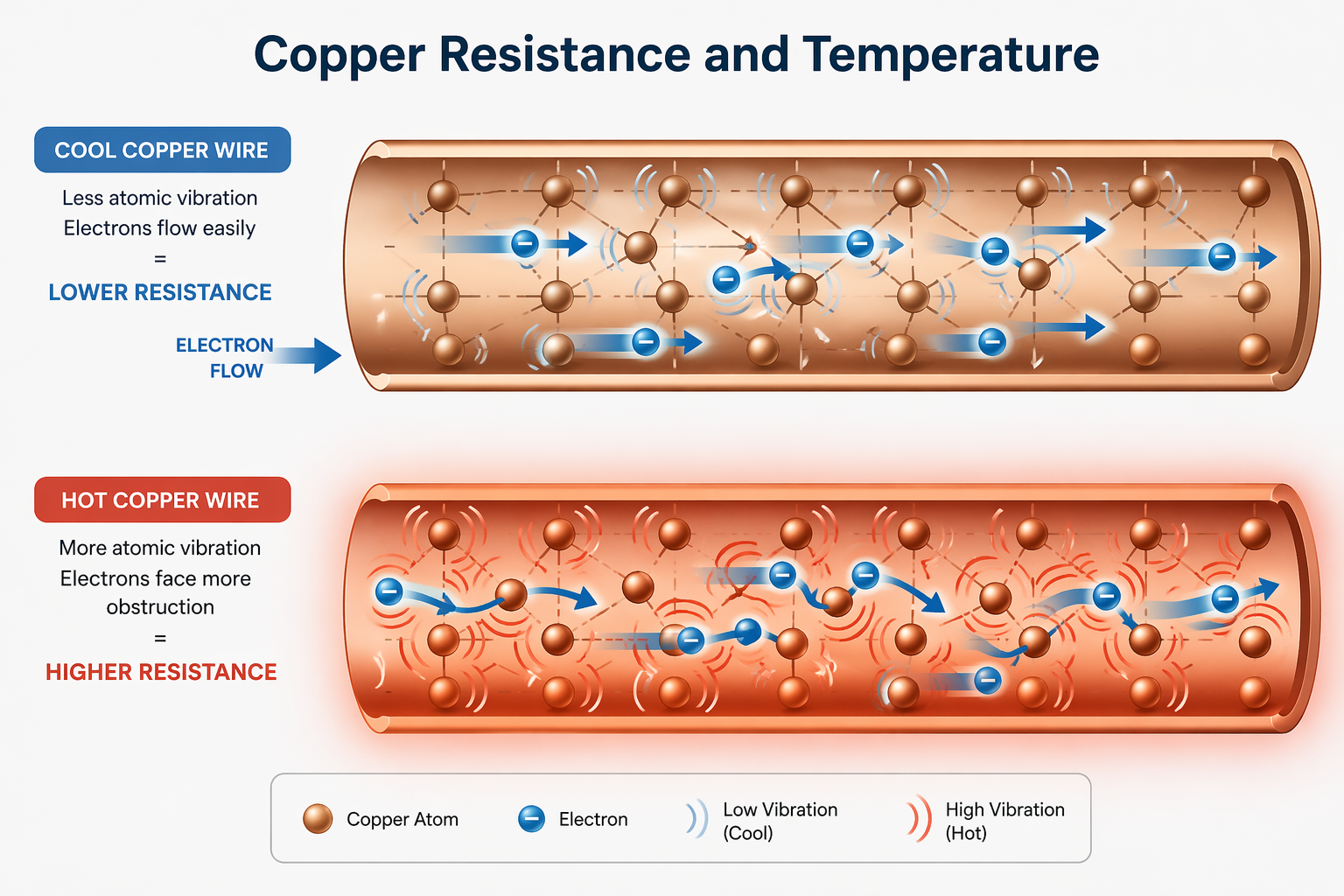
Think of it like trying to walk down a quiet, empty hallway. That's a coil at a cool temperature. The electrons (you) can move easily from one end to the other. Now, imagine that same hallway is filled with people who are jumping and shaking randomly. It becomes much harder to get through. This is what happens inside a copper wire as it heats up. The copper atoms themselves start vibrating more intensely, obstructing the path of the electrons.
This effect is predictable and is known as the "temperature coefficient of resistance2." For copper, the resistance increases by about 0.393% for every 1°C increase in temperature. This might not sound like much, but it adds up quickly.
The Impact of Temperature on Resistance
| Temperature | Resistance Increase (Approx.) | Example: 10 Ω Coil Becomes |
|---|---|---|
| 25°C (Baseline) | 0% | 10.0 Ω |
| 50°C | +9.8% | 10.98 Ω |
| 80°C | +21.6% | 12.16 Ω |
| 100°C | +29.5% | 12.95 Ω |
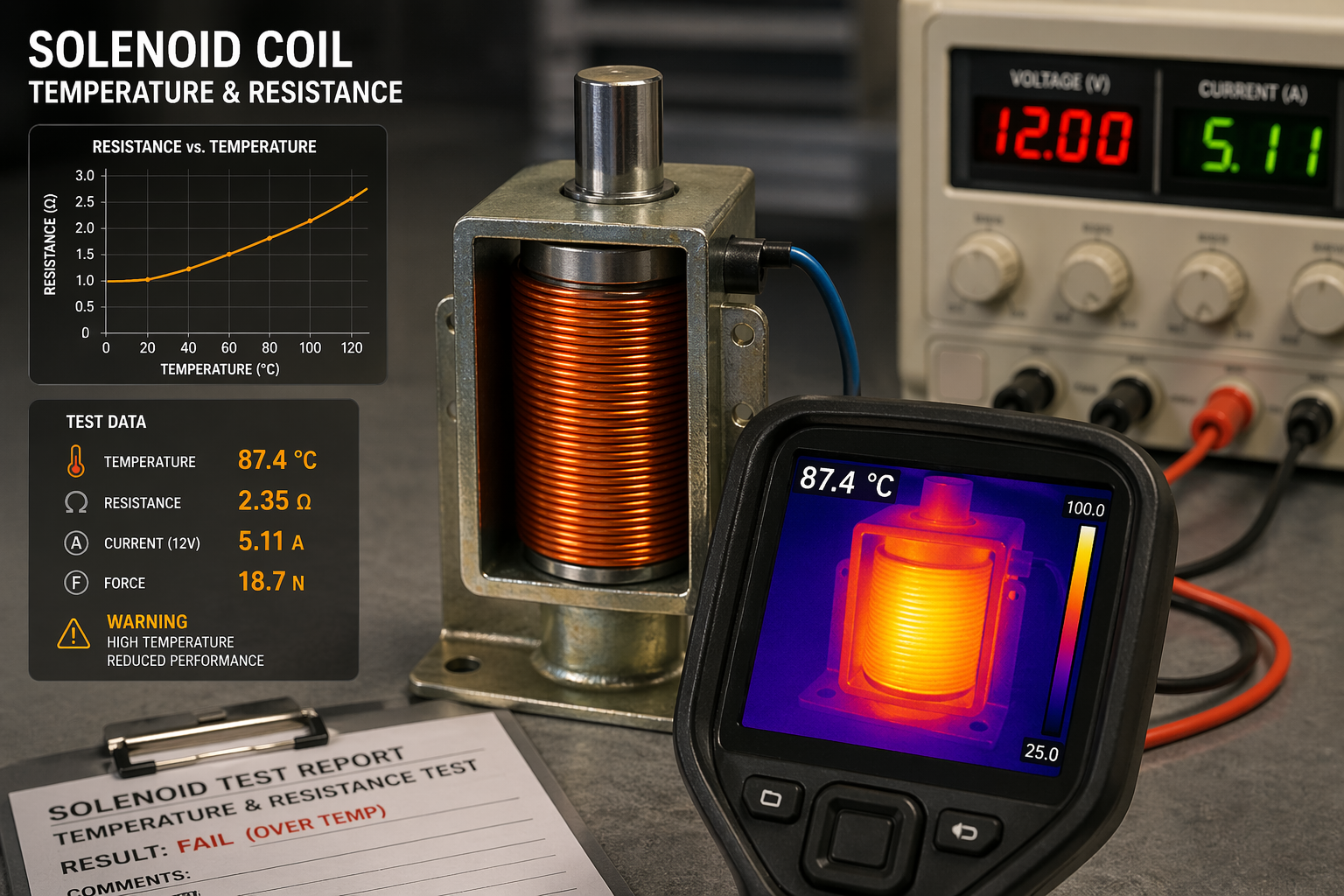
In my factory, we see this constantly. A coil that meets its 10-ohm spec perfectly at room temperature can easily measure over 12 ohms when running at its 80°C operating temperature. That 20%+ increase is not a minor detail; it's a fundamental change that directly impacts how the solenoid will function.
How Does Temperature Affect Solenoid Coil Performance and Efficiency?
Your solenoid feels weaker when it gets hot. This can cause your valve to stick or your actuator to fail, bringing your entire system to a halt. The problem is a direct link between heat and magnetic force.
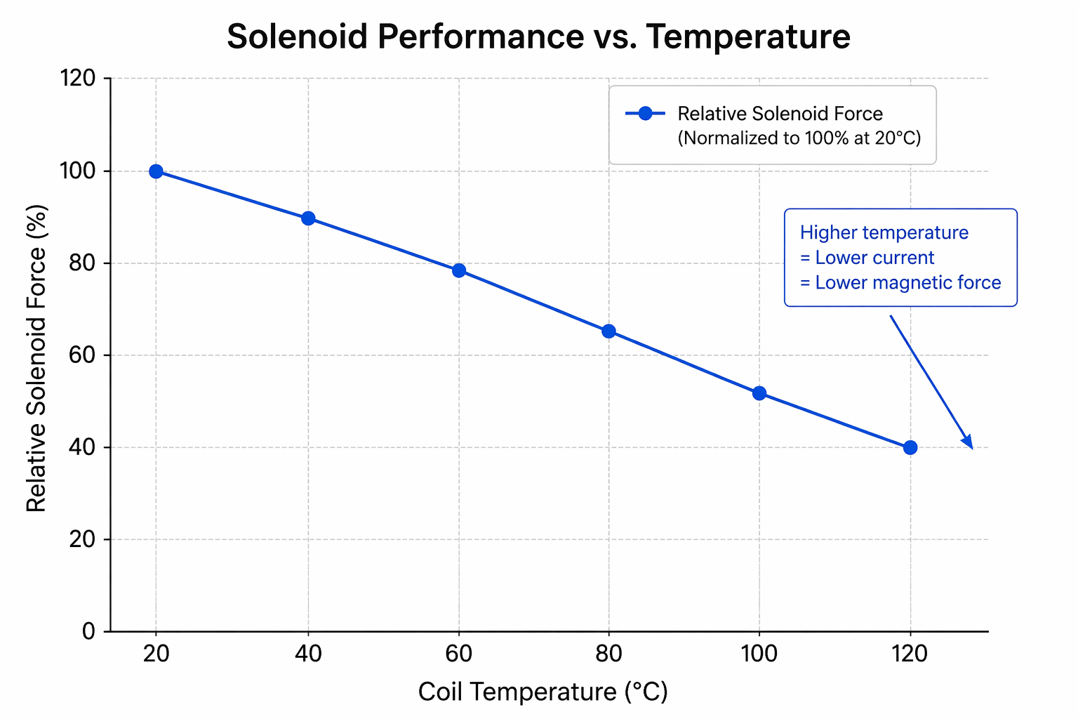
Higher temperatures increase coil resistance. According to Ohm's Law3, this reduces the current flowing through the coil. Since magnetic force is directly tied to current, a hotter coil is a weaker coil, degrading its performance and efficiency when you need it most.
I remember a classic case with a client who makes automotive valves for the European market. Their coils passed every single test in their cold-state lab. But in the real world, they were failing frequently during the summer, especially in cars with hot engine bays. The client was completely baffled and came to us for help.
We took apart the failed units and quickly identified the chain of events.
- High Ambient Heat: The engine bay reached temperatures over 80°C.
- Resistance Rises: The coil's temperature increased, causing its resistance to spike.
- Force Drops: With higher resistance, the current from the car's electrical system was no longer enough to generate the required magnetic force.
- Incomplete Actuation: The weakened force couldn't pull the valve plunger all the way open. It got stuck in a "half-open" state.
- Continuous Burn: The system, expecting the valve to open, kept supplying power to the coil. This continuous energization, instead of a short pulse, generated an enormous amount of heat that the coil was never designed to handle.
- Burnout: The coil's insulation melted, the wires shorted, and the component was destroyed.
This was a perfect example of a product that was qualified on paper but a failure in reality. The initial design completely underestimated the impact of temperature.
What Is the Relationship Between Copper Resistance and Heat in Coils?
You've seen a hot coil get even hotter, seemingly by itself. This runaway heating can quickly destroy the coil and even damage nearby components. This is caused by a dangerous feedback loop.
It's a vicious cycle. Initial heat increases the copper's resistance. This increased resistance causes the coil to generate even more heat from the electrical power it's converting. This new heat raises the resistance further, creating a thermal runaway4 that can lead to burnout.
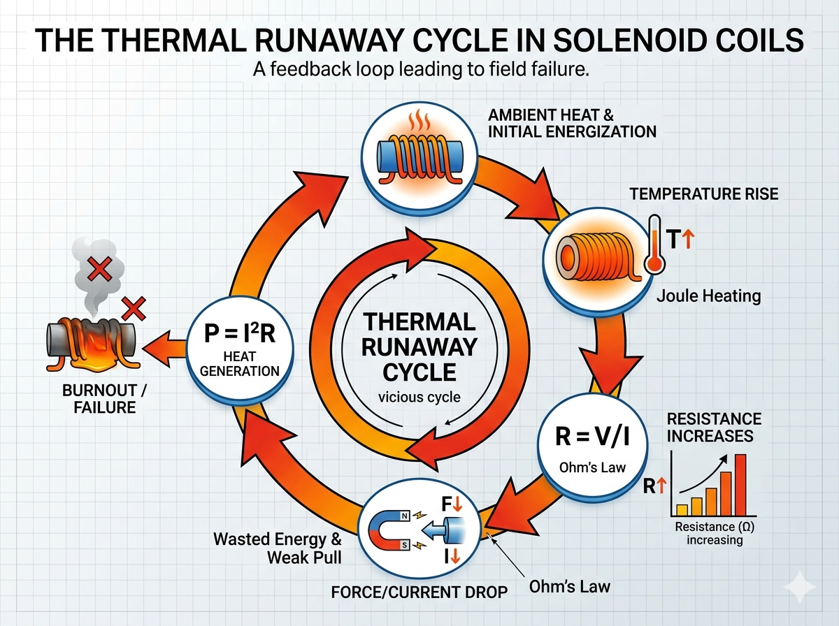
This phenomenon is rooted in the principles of power and heat. The power lost as heat in a coil is described by the formula P = I²R (Joule heating5). In the automotive valve case I mentioned, the failure was accelerated by this exact cycle. The valve getting stuck was the trigger.
Because the valve didn't fully actuate, the control system kept the power on. The coil was now in a state of continuous operation. This continuous power draw generated a steady stream of heat. Normally, a coil is designed to dissipate the heat from short, intermittent pulses. It was not designed to handle a constant flow of heat.
The temperature of the coil began to climb rapidly. As it climbed, so did the resistance. This created a feedback loop where the coil's inability to cool down was made worse by the fact that its own properties were changing to generate heat more effectively in a stuck state. The final result was inevitable: the temperature exceeded the melting point of the wire's enamel insulation, causing a short circuit and total failure. This shows exactly why testing a solenoid's performance only at room temperature is so misleading. The most catastrophic failure modes often only appear under high-heat, high-stress conditions.
How to Prevent Overheating Caused by Resistance Changes in Solenoid Coils?
You know overheating is a major risk, but you're not sure how to stop it. Simple fixes like using thicker wire aren't always effective and can add cost. A complete design approach is the only real solution.
Prevent overheating by designing the coil for its true operating temperature from the start. This involves using higher-class thermal insulation, optimizing the winding structure to manage heat, and improving the coil's physical design for better heat dissipation.
When we solved the problem for our automotive client, we didn't just use a thicker copper wire. That's a brute-force approach that adds cost and size. Instead, we re-engineered the coil from the ground up, focusing on three key areas.
Advanced Material Selection
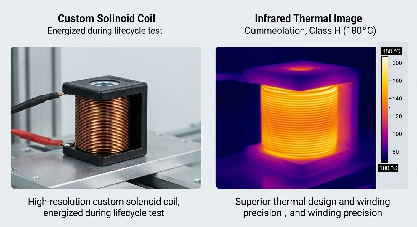
The first step was to upgrade the materials. Standard coils often use Class F enameled wire6, rated for 155°C. We switched to a Class H rated wire7, which can withstand up to 180°C. This immediately built a larger safety margin into the design, ensuring the insulation wouldn't break down even if the coil ran hotter than expected. We also selected a bobbin material with a higher thermal stability.
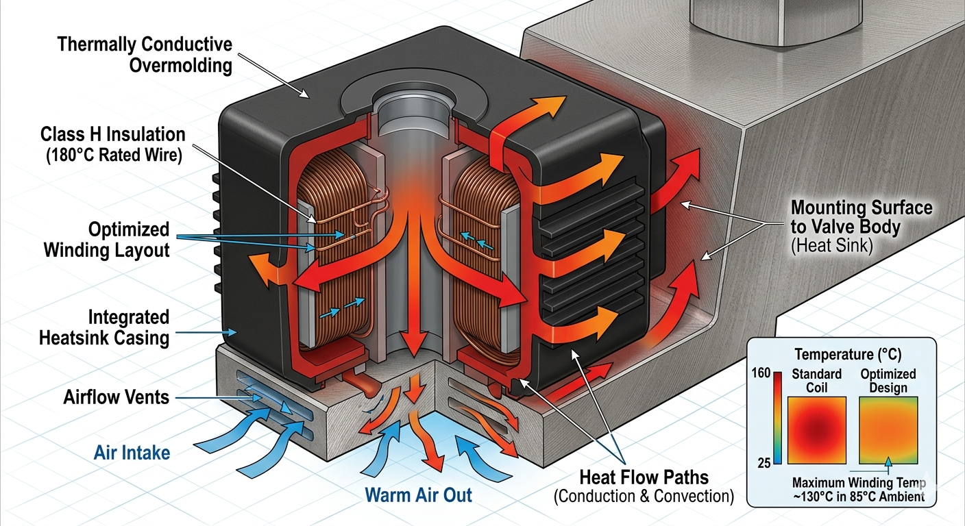
Smart Structural Design8
Next, we addressed heat dissipation. We optimized the winding density and pattern to create better pathways for heat to escape from the core of the coil. More importantly, we redesigned the plastic injection overmolding. By using a more thermally conductive polymer and designing the shape to maximize contact with the valve's metal body, we turned the entire valve assembly into a heat sink for the coil.
Proactive Testing Protocols9
Finally, we changed how we validate the product. We no longer sign off on a design after a simple room-temperature test. Our standard procedure now includes creating a high-temperature performance curve. We test the coil's magnetic force at its maximum rated operating temperature to ensure it still delivers the required power. This prevents "lab-qualified, field-failed" scenarios by simulating the worst-case environment before the product ever ships.
What Temperature Range Is Safe for Solenoid Coil Operation?
You need a simple, clear "safe" temperature number for your coil. Without it, you are just guessing and accepting a huge risk of failure. The answer is defined by the coil's insulation class.
The safe operating temperature is determined by the coil's thermal insulation class10. Common classes are B (130°C), F (155°C), and H (180°C). This value is the maximum total temperature the coil can withstand continuously, which includes both ambient heat and its own self-heating.
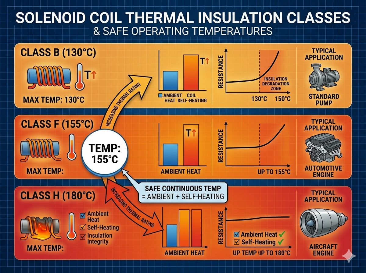
This is one of the most misunderstood specifications in solenoid design. The class rating is not how hot the coil can get; it's the maximum total temperature its insulation can handle without degrading over time. This total temperature is calculated with a simple formula:
Maximum Coil Temperature11 = Ambient Temperature + Temperature Rise (Self-Heating)
For example, if you are using a standard Class F coil, its maximum allowable temperature is 155°C. If your machine operates in an environment with an ambient temperature of 90°C, the temperature rise from the coil's own operation cannot exceed 65°C (155°C - 90°C). If it heats itself by 70°C, it will slowly cook itself to death, even if it seems to be working fine at first.
Common NEMA Insulation Classes12
| Class | Maximum Temperature | Typical Application |
|---|---|---|
| Class A | 105°C | Older designs, low-power applications |
| Class B | 130°C | General industrial equipment |
| Class F | 155°C | Common standard for motors and solenoids |
| Class H | 180°C | High-demand, high-temperature environments |
| Class C | >220°C | Extreme applications (aerospace, specialty) |
Choosing the right class is not about over-engineering; it's about matching the component to the reality of its environment. The failure of our client's automotive coil happened because the combined ambient heat and the self-heating from being stuck far exceeded its Class F rating.
Conclusion
The core issue isn't that resistance changes with temperature. It's whether you designed your solenoid coil for its real-world operating temperature, not just for the lab.
Understanding atomic motion's impact on resistance helps in designing solenoids that perform reliably under varying temperatures, preventing costly failures. ↩
Knowing the temperature coefficient of resistance is crucial for predicting how solenoid coils will behave under different temperatures. ↩
Understanding Ohm's Law is crucial for grasping how temperature affects solenoid coil resistance and performance, impacting product reliability. ↩
Learning about thermal runaway can help in designing solenoids that avoid destructive feedback loops and maintain performance. ↩
Understanding Joule heating can help in designing solenoids that manage heat effectively and prevent overheating. ↩
Understanding the use of Class F enameled wire can help in designing solenoids that withstand higher temperatures. ↩
Using Class H rated wire can enhance solenoid performance in high-temperature environments, preventing failure. ↩
Exploring smart structural design can lead to solenoids that dissipate heat better and perform reliably under stress. ↩
Implementing proactive testing protocols can prevent lab-qualified, field-failed scenarios by simulating real-world conditions. ↩
Understanding thermal insulation classes helps in selecting the right solenoid for specific temperature conditions. ↩
Calculating the maximum coil temperature ensures solenoids operate within safe limits, preventing overheating and failure. ↩
Knowing NEMA insulation classes helps in selecting solenoids that can withstand specific environmental conditions. ↩