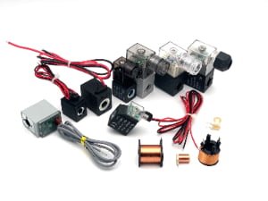

24V Solenoid Coil: Selection, Power, Wiring, and OEM Design Guide
A 24V solenoid coil label looks simple, yet it often leads buyers to assume that any coil marked 24V will operate their valve reliably. That assumption can create overheating, weak actuation, installation delays, and costly replacement errors. I recommend treating voltage as the first check, then evaluating the full electrical, mechanical, and thermal requirement.
A 24V solenoid coil is designed for a nominal 24-volt supply, but voltage alone does not define its power, resistance, magnetic force, duty cycle, dimensions, connection, or valve compatibility[^1]. For a reliable selection, I start with the supply type, then confirm the valve interface, magnetic requirement, power, operating duty, temperature conditions, connection method, and validation test plan.
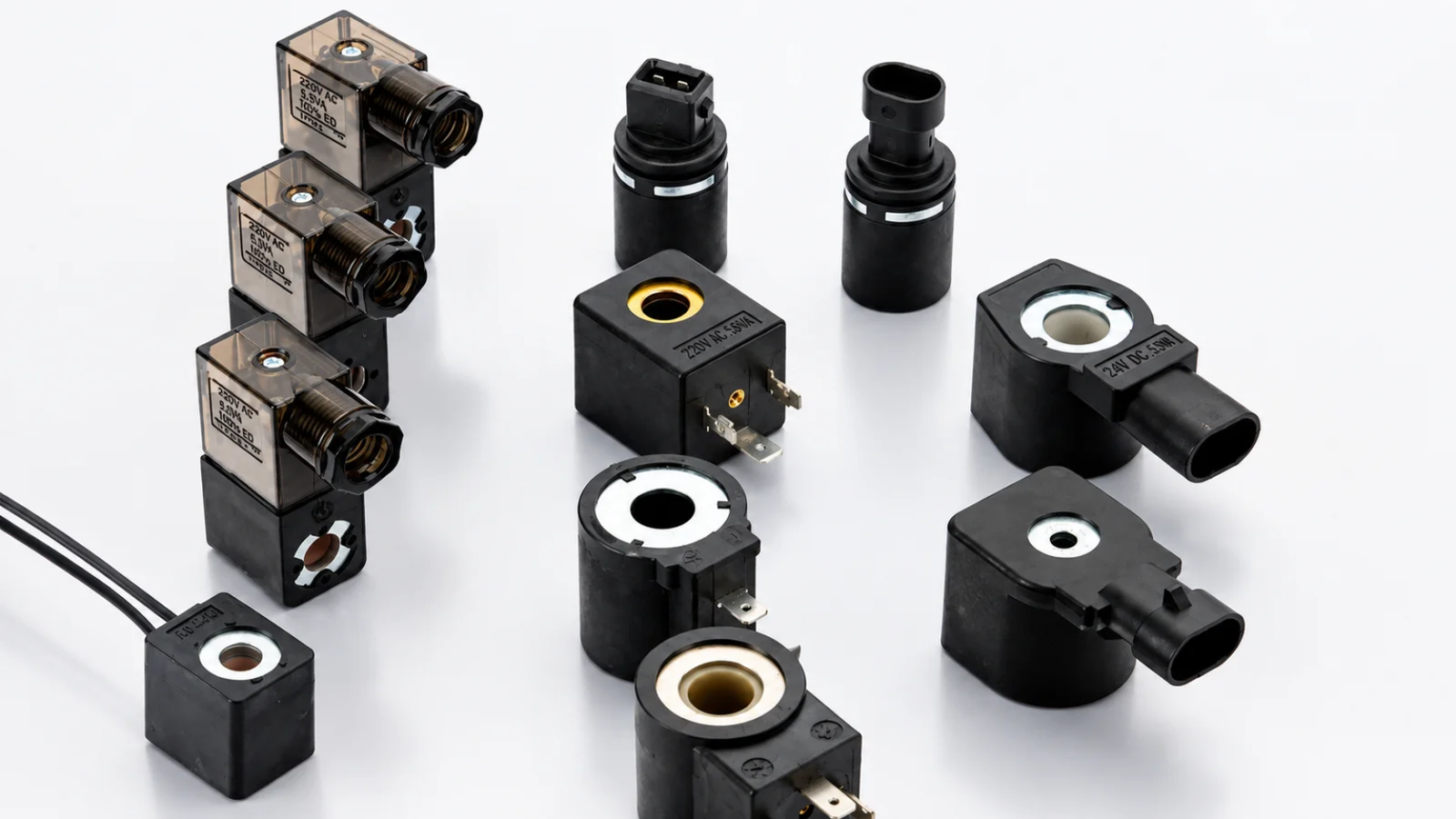
For OEM engineers and technical buyers, the important question is not simply, “Is this a 24V coil?” The better question is, “Will this particular coil operate this valve under real voltage, temperature, and duty-cycle conditions?” That distinction separates a catalog match from an engineered solution.
What Is a 24V Solenoid Coil and How Does It Work?
A 24V marking can give a false sense of compatibility. Buyers often find a coil with the right voltage, install it on a valve, and only later discover that the bore, connector, magnetic force, or heat rise is wrong. I see this problem most often when replacement decisions are made from photos or voltage labels alone.
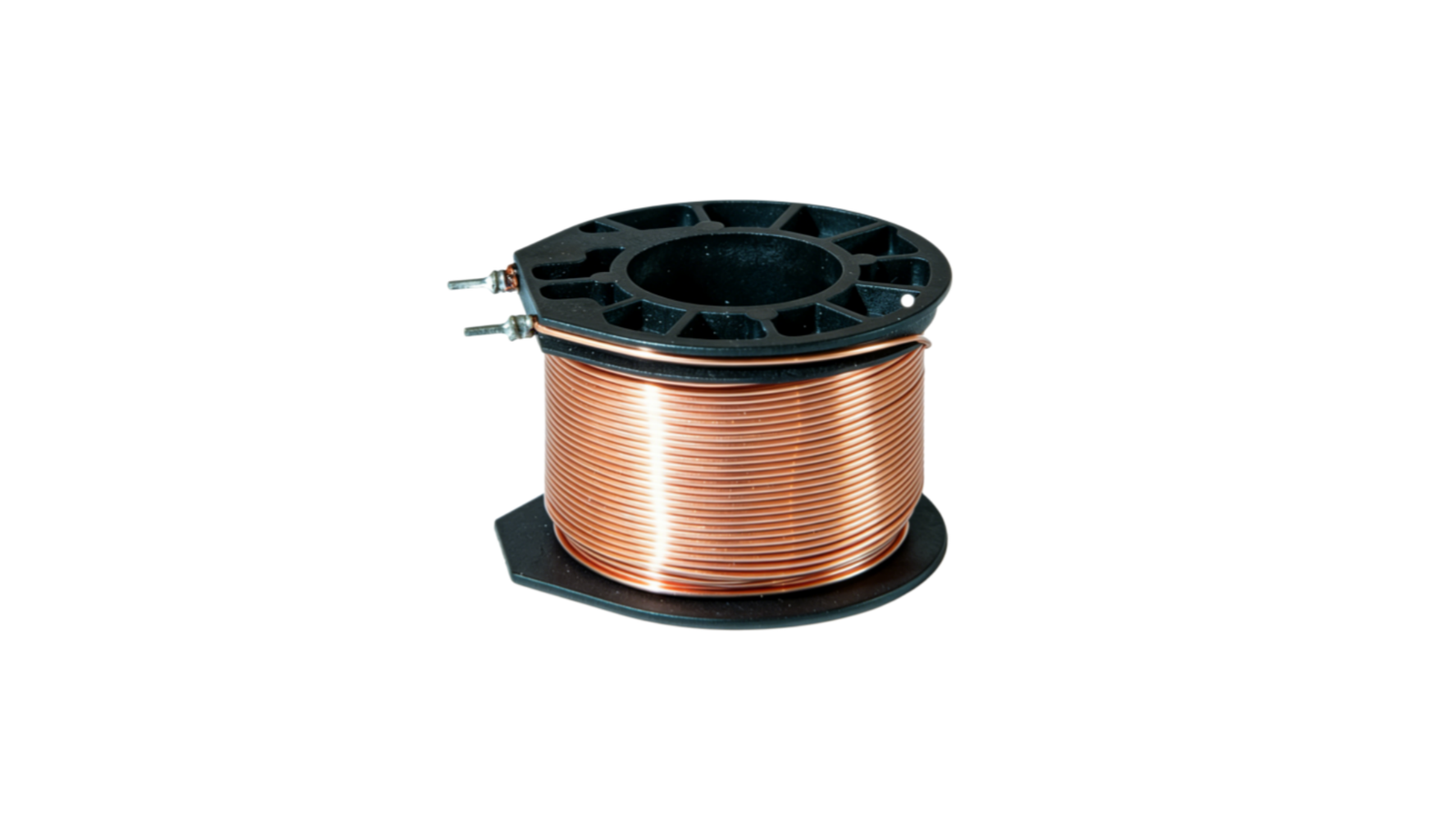
A 24V solenoid coil is an electromagnetic winding designed to operate from a nominal 24V electrical supply. When current flows through the winding, it creates a magnetic field that acts through the valve’s core and armature system.[^2] The coil is only one part of the complete magnetic circuit, so its voltage rating does not confirm full valve compatibility.

24VDC and 24VAC Are Different Electrical Designs
A 24VDC solenoid coil is designed for direct current. Its performance depends mainly on DC resistance, current, winding construction, copper temperature, and the magnetic circuit.
A 24VAC solenoid coil is designed for alternating current. AC designs must account for alternating magnetic flux, inductive effects, inrush behavior, hum, and in some cases shading-ring construction.[^3] A 24VAC coil is not a direct substitute for a 24VDC coil, even when the connector and outside dimensions look similar.[^4]
| Feature | 24VDC Coil | 24VAC Coil |
|---|---|---|
| Supply type | Direct current | Alternating current |
| Main electrical reference | Resistance and DC current | Impedance and AC behavior |
| Typical control source | PLC, DC power supply, industrial control panel | Transformer-based AC system |
| Polarity concern | Relevant with diode or LED circuits | Usually not applied in the same way |
| Interchangeable with the other type? | No | No |
In our engineering reviews, I treat the following statement as non-negotiable:
“24V” only defines the nominal supply voltage. It does not tell an engineer the coil's power, resistance, magnetic performance, duty cycle, temperature rise, or mechanical compatibility.
The magnetic force available at the armature depends on more than the coil winding.[^5] It also depends on the valve’s armature tube, core material, air gap, spring force, pressure conditions, and assembly tolerances. A coil that performs well on one valve platform can fail to pull in on another valve with a different magnetic circuit.
For that reason, I do not recommend selecting a 24V pneumatic solenoid coil from voltage alone. The valve interface and operating conditions must be part of the decision.
How Do Power, Resistance, and Current Relate in a 24V Solenoid Coil?
Power ratings can confuse buyers because two coils with the same 24VDC label can draw very different currents. A higher-power coil can appear stronger on paper, but it also creates more heat. If an engineer ignores that trade-off, a coil that works at room temperature can become unreliable after prolonged operation.
For a DC 24V solenoid coil, power, current, and resistance are closely related: current equals power divided by voltage, while approximate resistance equals voltage squared divided by power[^6]. A 24VDC, 4.8W coil draws about 0.2A and has an approximate nominal resistance of 120Ω at the assumed measurement temperature.
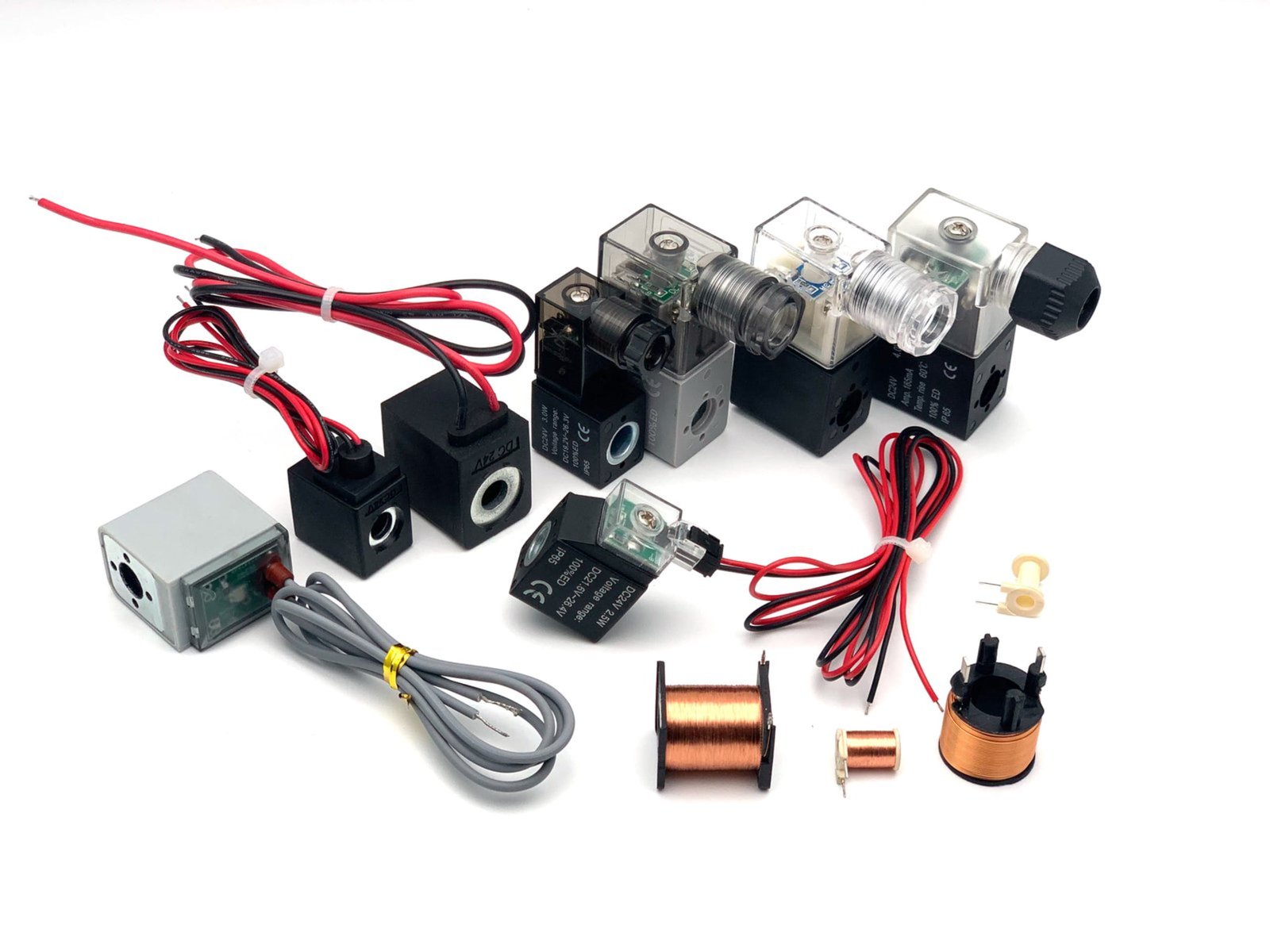
A Practical 24VDC / 4.8W Example
For a simple DC calculation:
Current
[ I = P / V ]
Approximate resistance
[ R = V² / P ]
For a 24VDC, 4.8W coil:
- Voltage: 24V
- Power: 4.8W
- Current: 4.8W ÷ 24V = 0.2A
- Approximate resistance: 24² ÷ 4.8 = 120Ω
This calculation is useful for preliminary electrical planning. It helps buyers estimate control-output loading, cable current, fuse sizing, and power-supply capacity.
However, I do not treat 120Ω as a universal resistance specification for every 24V coil. Real production measurements vary due to:
- Copper resistance tolerance
- Winding design and wire diameter
- Measurement temperature
- Terminal and lead-wire resistance
- Coil construction
- Manufacturing variation within the approved specification
Why Hot-State Resistance Matters
Copper resistance rises as temperature rises.[^7] A coil that measures close to 120Ω at room temperature will show a higher resistance after it heats up. Higher resistance reduces current at a fixed DC voltage.[^8] That reduction can lower the available magnetic margin.
This is why a coil that pulls in successfully when cold can become less reliable after extended energization. In my view, hot-state operation matters more than a few successful room-temperature actuations.
A robust validation plan should include:
- Cold pull-in testing at nominal voltage.
- Minimum-voltage pull-in testing at the lowest expected supply voltage.
- Hot-state pull-in testing after the coil reaches stabilized temperature.
- Continuous-duty temperature-rise testing where 100% duty is required.
- Repeat switching tests on the actual valve assembly.
Higher Wattage Is Not Automatically Better
A higher-wattage 24V solenoid coil often draws more current and can provide additional magnetic force in a suitable magnetic circuit. Yet more wattage also produces more heat.[^9] That heat affects insulation life, nearby plastic components, valve seals, connectors, and control-panel thermal conditions.[^10]
Higher wattage is not automatically better.
The engineering objective is not maximum wattage. The objective is:
Sufficient magnetic force under worst-case operating conditions with acceptable temperature rise—not maximum wattage.
At SolenElec, we evaluate power as part of the complete coil-and-valve system. A lower-power coil with proper magnetic design and thermal control can be a better production solution than an oversized coil that creates unnecessary heat.
For a deeper qualification approach, readers can also review our guide on how to test a solenoid coil: resistance, insulation, and pull-in tests.
12V vs 24V Solenoid Coil: Which Voltage Should You Choose?
For a dedicated OEM comparison, see 12V vs 24V Solenoid Coil: Which Voltage Should Pneumatic OEMs Standardize?. Voltage selection can become unnecessarily complicated when teams compare 12V and 24V in isolation. The real risk is introducing a second control voltage just for one component. That decision adds wiring, conversion, spare-parts, and maintenance complexity without always providing a clear system benefit.
For the same power rating, a 24V solenoid coil draws half the current of a comparable 12V coil.[^11] I normally recommend 24VDC for industrial pneumatic equipment that already uses 24VDC control power, because it aligns with common PLC and automation architectures while reducing current in the wiring and connector path.
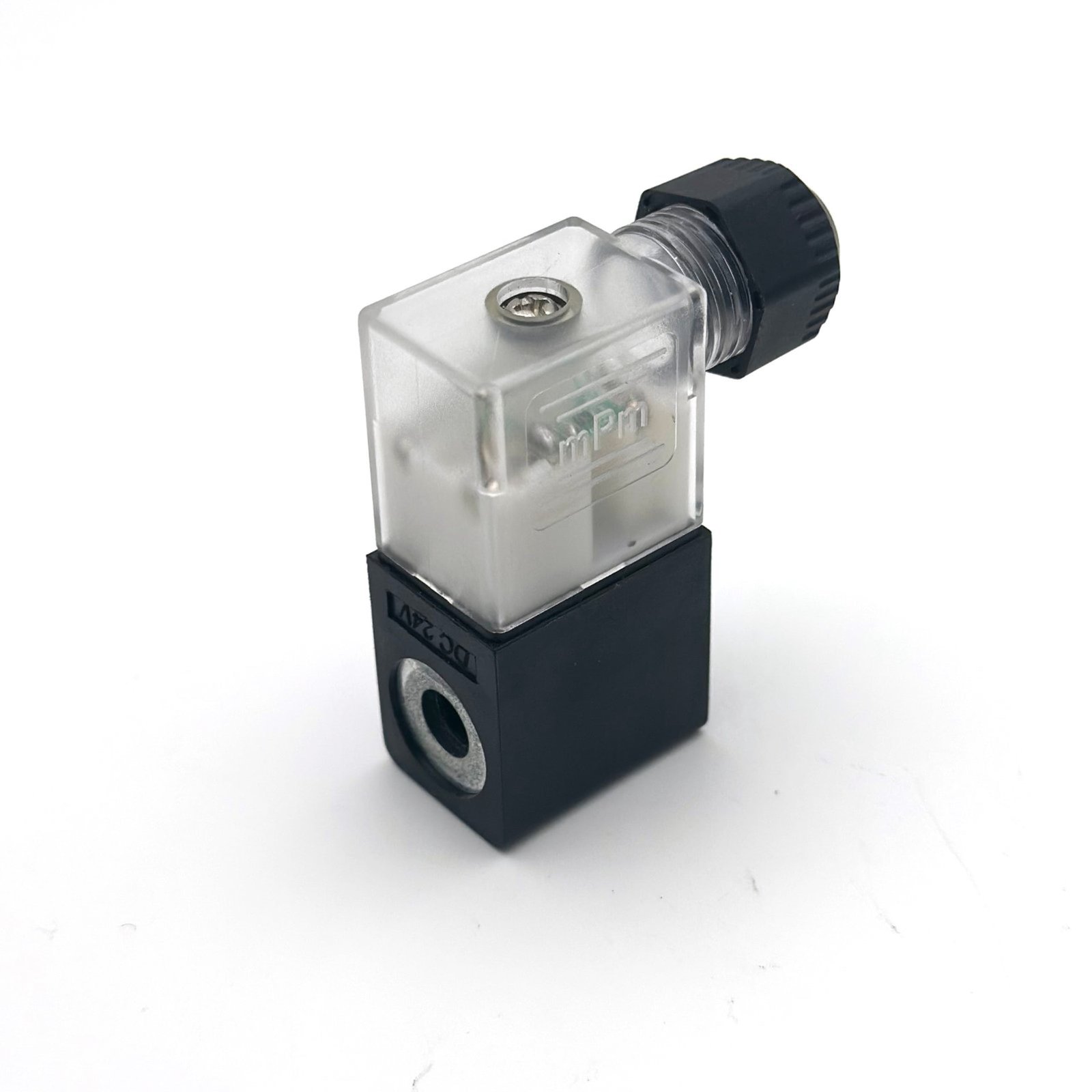
Equal-Power Electrical Comparison
The following comparison uses the same 4.8W coil power level.
| Parameter | 12V Coil | 24V Coil |
|---|---|---|
| Voltage | 12VDC | 24VDC |
| Approximate current | 0.4A | 0.2A |
| Approximate resistance | 30Ω | 120Ω |
| Power | 4.8W | 4.8W |
At equal power, the 24V version uses lower current. That does not automatically mean every 24V solenoid coil is better than every 12V coil. It does mean that 24VDC often fits industrial control systems more efficiently.
Why 24VDC Often Fits Industrial Equipment Better
For industrial pneumatic equipment with an existing 24VDC control architecture, I normally prefer a 24VDC coil instead of adding 12V solely for the solenoid. The reasons are practical:
- Lower current for equal power: Lower current reduces conductor loading.
- Reduced voltage-drop sensitivity in long cable runs: Cable resistance still matters, but lower current lowers voltage loss.
- Simpler PLC integration: Many industrial PLC outputs and control systems use 24VDC.[^12]
- Simpler power architecture: One control voltage reduces conversion devices and spare-part complexity.
- Better connector margin: Lower current can reduce contact heating when the connector system is correctly specified.
For example, a long cable run with a marginal connector can create a measurable voltage drop. If the coil already operates close to its pull-in threshold, that lost voltage can affect switching reliability. I therefore recommend checking the actual voltage at the energized coil, not only the power-supply rating at the control cabinet.
When 12V Remains the Right Choice
A 12V solenoid remains appropriate when the equipment already uses a 12V architecture. Common examples include:
- Battery-powered equipment
- Certain mobile machines
- Vehicle electrical systems
- Legacy 12V control platforms
- Equipment where a dedicated 12V supply is already stable and required
The voltage should follow the equipment architecture. It should not be selected independently because one voltage appears more convenient in a coil catalog.
How Do You Select a 24V Solenoid Coil for a Pneumatic Valve?
A pneumatic valve can appear mechanically simple, but reliable coil selection requires several checks in the correct order. A 24V label does not confirm that the coil fits the armature tube, develops enough pull-in force, tolerates the required duty cycle, or remains safe at the expected ambient temperature.
To select a 24V solenoid coil for a pneumatic valve, confirm the DC or AC supply, actual voltage range, valve interface, magnetic requirement, power rating, duty cycle, thermal environment, connection method, and test requirements. Two 24VDC coils should never be considered interchangeable only because they share the same nominal voltage.

Step 1: Confirm the Electrical Supply
I begin with the actual available supply, not the nominal label on a machine drawing.
Check:
- 24VDC or 24VAC
- Minimum voltage at the coil terminals
- Maximum supply voltage
- PLC or relay output type
- Available output current
- Polarity requirements for coils with LEDs, diodes, or suppression circuits
A diode-protected DC coil has polarity requirements. Reversing polarity can prevent operation or damage the circuit, depending on the design.
Step 2: Confirm the Mechanical Interface
Mechanical compatibility is often the first reason a replacement coil fails. Buyers should confirm:
- Bore diameter
- Armature tube diameter
- Coil height
- Outside diameter or width
- Retaining method
- Connector orientation
- Clearance around the installed valve manifold
A coil with the right bore but excessive height can interfere with adjacent valves. A coil with matching dimensions but poor alignment with the magnetic circuit can still fail electrically.
Step 3: Confirm Power and Magnetic Requirement
The solenoid coil must develop enough force to pull in and hold the valve mechanism under real operating conditions. I review:
- Rated coil power
- Required pull-in force
- Holding force requirement
- Armature air gap
- Return spring force
- Valve pressure and load conditions
- Minimum operating voltage
Step 4: Confirm Duty Cycle and Thermal Conditions
Continuous duty requires more than a successful short test. A 100% ED coil must remain within its intended thermal limits during sustained energization.
Check:
- Continuous or intermittent duty
- Maximum ON time
- OFF-time and cooling conditions
- Ambient temperature
- Nearby heat sources
- Ventilation
- Dense manifold installation
- Expected coil surface temperature
For further duty-cycle analysis, I recommend our article, what is the difference between continuous and intermittent duty solenoids?.
Step 5: Confirm Connection and Protection
Connection options can include:
- DIN connectors
- Flying leads
- Plug-in harnesses
- Molded cable assemblies
Additional features may include:
- LED indicators
- Diodes
- Rectifiers
- Surge suppression
- Defined IP protection levels
At SolenElec, one relevant engineering platform uses a 24VDC, 4.8W, Ø15 mm pneumatic coil configuration. In a defined version, it supports 100% ED, an IP65 configuration, plug-in harness options, and indicator options.
In one upgrade project, the base electrical architecture remained 24VDC and 4.8W, while the Ø15 mm mounting interface was retained. The connection changed from flying leads to a plug-in harness, and an indicator was added. The lesson was straightforward:
A useful product upgrade does not need to change every parameter. Preserve interfaces that already work and change the features that create measurable installation, service, or application value.
Still, I do not consider a plug-in connector an automatic upgrade. A plug-in connection is only an upgrade if contact reliability, retention, polarity, and sealing remain reliable. Convenience alone is not enough.
Step 6: Validate on the Actual Valve
The final decision should be based on the complete valve assembly. I recommend validating:
- Cold pull-in
- Pull-in at minimum supply voltage
- Hot-state pull-in
- Temperature rise
- Continuous-duty operation
- Repeated switching consistency
- Connector retention and electrical continuity
- Environmental protection in the installed configuration
For replacement projects, our solenoid valve coil replacement drop-in compatibility checklist provides a more detailed interchangeability review.
What Information Is Needed for a Custom 24V Solenoid Coil?
A custom project often starts with an incomplete request: a photo, a 24V marking, and a request for a quotation. That information is enough to begin a discussion, but it is not enough to freeze a design. Missing operating data creates prototype uncertainty and can delay qualification.
For a custom 24V solenoid coil, I recommend providing the valve application, supply type and voltage range, interface dimensions, duty cycle, thermal conditions, connection requirements, protection level, prototype quantity, annual volume, and required compliance documents. These inputs let the manufacturer evaluate whether an existing platform or a new coil design is justified.
OEM Information Checklist
| Requirement | Information to Provide |
|---|---|
| Application | Valve type or equipment type |
| Supply | 24VDC or 24VAC |
| Voltage range | Minimum, nominal, and maximum voltage |
| Valve interface | Drawing, 3D file, or physical sample |
| Bore | Diameter and tolerance |
| Coil envelope | Height, width, and outside diameter |
| Duty cycle | Continuous or intermittent operation |
| Temperature | Ambient, nearby heat, fluid, and installation conditions |
| Connection | DIN, flying lead, plug-in, or harness requirement |
| Lead wire | Type, length, and temperature requirement |
| Circuit | LED, diode, rectifier, or surge suppression |
| Protection | Required IP level in the final assembly |
| Prototype | Required sample quantity and test plan |
| Production | Estimated annual volume |
| Compliance | Required standards and documents |
Buyers should verify certifications and compliance documents for the exact product configuration and target market. A document for one coil platform, cable material, or connector configuration does not automatically apply to every modified version.
Specify the Outcome Before the Winding Construction
I strongly recommend that OEM buyers define what the coil must achieve before telling the manufacturer exactly how to wind it.
Tell the coil manufacturer what the coil must achieve before telling them exactly how it must be wound.
The customer usually needs to define:
- Supply voltage
- Available installation space
- Valve interface
- Duty cycle
- Ambient and operating temperature
- Required function
- Connection requirement
- Validation criteria
Unless an existing coil must be copied exactly for approved replacement reasons, the customer often does not need to dictate:
- Exact wire diameter
- Exact number of turns
- Exact winding pattern
- Exact internal construction
Those details are engineering outputs. The manufacturer’s engineering team should select a winding design that meets the electrical, magnetic, thermal, and manufacturing requirements.
A custom coil should solve a real problem, such as:
- Insufficient magnetic margin
- Excessive heat rise
- Limited installation space
- Poor connector accessibility
- Required LED or suppression function
- Improved sealing requirement
- Production assembly efficiency
- A validated replacement interface
A custom coil should solve a real electrical, thermal, mechanical, connection, or manufacturing problem—not simply create a custom part number.
How Can You Reduce Custom Solenoid Coil Prototype Time?
Prototype time expands when the engineering team must infer critical conditions from incomplete information. A physical sample helps, but a sample without duty cycle, voltage range, or valve information still leaves major risks unresolved.
The fastest route to a useful custom solenoid coil prototype is to provide a valve or interface drawing, an existing sample where available, electrical conditions, duty cycle, temperature limits, connection requirements, prototype quantity, and expected annual volume. A photo and “24VDC” can start a conversation, but they cannot freeze an OEM coil design.
| Information Provided | Engineering Uncertainty | Prototype Evaluation |
|---|---|---|
| Photo + “24V” | Very high | More clarification required |
| Coil dimensions + 24V | High | Basic feasibility only |
| Coil drawing + electrical requirements | Medium | Better starting point |
| Valve interface + operating conditions + drawing/sample | Low | Most efficient engineering review |
In our OEM work, I have found that the best early-stage package includes both physical and functional information. A drawing tells us the space and mounting constraints. A sample reveals practical details that drawings sometimes omit. Electrical and thermal conditions tell us whether the existing electrical platform is suitable.
SolenElec supports OEM and ODM coil development from design and prototyping through mass production. Our manufacturing context includes coil winding, injection molding, assembly, incoming material inspection, outgoing inspection, and MES-based traceability. However, each buyer should still evaluate the specific product, validation evidence, applicable documentation, and production-control plan for the intended application.
For broader valve-focused selection criteria, readers can continue to pneumatic solenoid coils: how to select the right coil for your valve.
Frequently Asked Questions
Is a 24VDC solenoid coil the same as a 24VAC solenoid coil?
No. A 24VDC solenoid coil and a 24VAC coil use different electrical operating principles and are not interchangeable. DC coils are designed around resistance and DC current, while AC coils must account for AC impedance and alternating magnetic behavior. Always match the coil to the actual supply type.
What resistance should a 24V solenoid coil have?
There is no universal resistance value for a 24V solenoid coil. Resistance depends on the power rating and winding design. For example, a 24VDC, 4.8W coil has an approximate nominal resistance of 120Ω, but measured values change with temperature, tolerance, and construction.
Can I replace a 24V solenoid coil with another 24V coil?
Not safely based on voltage alone. The replacement must also match the supply type, power, bore, dimensions, magnetic circuit, duty cycle, connector, environmental protection, and valve function. I recommend testing the candidate coil on the actual valve under cold and hot operating conditions.
Is a higher-power 24V solenoid coil stronger?
A higher-power coil can provide more magnetic force in some designs, but it also generates more heat. Higher wattage is not automatically better. The correct coil has enough pull-in and holding margin at the minimum operating voltage while maintaining acceptable temperature rise during the required duty cycle.
Should I choose 12V or 24V for a pneumatic solenoid valve?
For industrial pneumatic equipment that already uses 24VDC controls, I normally recommend a 24VDC solenoid coil. It aligns with PLC control systems and uses lower current than an equal-power 12V coil. A 12V coil remains appropriate when the equipment already operates from a 12V electrical architecture.
Conclusion
A 24V solenoid coil should be selected from the equipment and valve requirements, not from a 24V label in a catalog. I recommend following this order: 24V supply → valve interface → required magnetic performance → power → duty cycle → thermal conditions → connection → validation. The strongest design is not always the highest-wattage option. It is the coil that performs reliably at minimum voltage, after heating, and within the actual valve assembly. The winding, insulation, and magnetic-geometry decisions behind that result are covered in How Should You Design a Coil for Better Performance and Long-Term Reliability. The winding, insulation, and magnetic-geometry decisions behind that result are covered in How Should You Design a Coil for Better Performance and Long-Term Reliability. If your existing coil does not meet dimensional, thermal, magnetic, or connection requirements, provide SolenElec with your valve drawing or sample, supply conditions, duty cycle, operating temperature, connection requirement, prototype quantity, and expected annual volume for an engineering review.