What Are High-Performance Solenoids? How They Work and What Defines Their Performance
High performance solenoids can create procurement problems when buyers compare only force, wattage, or a short catalog description. A solenoid may look strong in a bench test but fail to pull in at low voltage, after heating, or under real mechanical load. I recommend defining the full operating requirement first, then validating the solenoid against it.
A high-performance solenoid is an electromagnetic actuator engineered to meet demanding combinations of force, stroke, response time, duty cycle, thermal stability, repeatability, size, and service-life requirements[^1]. High force alone does not make a solenoid high performance. The right design must deliver the required mechanical output reliably under the application’s electrical, thermal, environmental, and life-cycle conditions.
I find that the most useful way to evaluate a solenoid is not to ask whether it is “powerful.” I ask whether it can perform a defined motion, at a defined force and speed, for a defined duty cycle, in the real product environment. That shift turns a marketing claim into an engineering decision.
What Is a High-Performance Solenoid?
A high-performance solenoid is an electromagnetic actuator designed to meet several demanding requirements at the same time, rather than maximizing one specification. It must provide adequate force through the required stroke while operating within limits for temperature, response time, package size, power input, repeatability, and expected service life.
A high-performance solenoid is not simply a high force solenoid. It is a solenoid that consistently meets the required force, stroke, timing, duty-cycle, thermal, environmental, and durability targets with sufficient engineering margin. A larger, hotter, or shorter-life actuator may produce more peak force but still be unsuitable for the actual application.
The term “high performance” only has meaning when the application conditions are clear. A compact appliance latch, a pneumatic valve actuator, and an automated dispensing mechanism can all need high performance, but their priorities may be very different.
Performance Is a Combination of Requirements
For example, one design may need fast pull-in time within a limited installation space. Another may need stable holding force during extended energization. A third may need repeatable switching over a high cycle count in a warm, enclosed appliance.
I do not treat these requirements as separate checkboxes. They interact:
- A smaller package can limit winding volume and thermal dissipation.
- A longer stroke generally changes the available magnetic force.
- A higher duty cycle increases heat accumulation.
- Higher temperature increases coil resistance.
- More force can require more electrical input, a different magnetic circuit, or both.
- Faster response can depend on armature mass, spring rate, drive voltage, and friction.
| Performance Metric | What It Means |
|---|---|
| Force | Enough pull or push force at the required stroke |
| Force-to-size ratio | Useful force within limited installation space |
| Response time | Fast and repeatable actuation |
| Duty cycle | Ability to operate across the required ON/OFF profile |
| Thermal performance | Maintains required operation after heating |
| Repeatability | Consistent movement and timing |
| Service life | Meets the defined cycle-life target |
| Environmental capability | Performs across required temperature, vibration, moisture, dust, and other conditions |
Why a Single Specification Is Not Enough
A catalog may list a maximum force value, but that number can be misleading without its test position. Solenoid force typically changes substantially as the air gap changes.[^2] A design may produce strong holding force when the armature is seated but have insufficient pull-in force at the beginning of the stroke.
Similarly, a coil may operate well when cold at nominal voltage, yet lose useful margin after thermal stabilization or at the lower end of the supply-voltage range.
I recommend evaluating high performance solenoids as a performance envelope, not as one headline number.
For OEM and ODM projects, this approach helps procurement teams compare suppliers on evidence rather than broad claims. SolenElec describes its role as supporting customized coil and solenoid projects from design and prototyping through volume manufacturing. Buyers should still request the relevant drawings, test conditions, material specifications, and compliance documents for the exact part under consideration.
How Do High-Performance Solenoids Work?
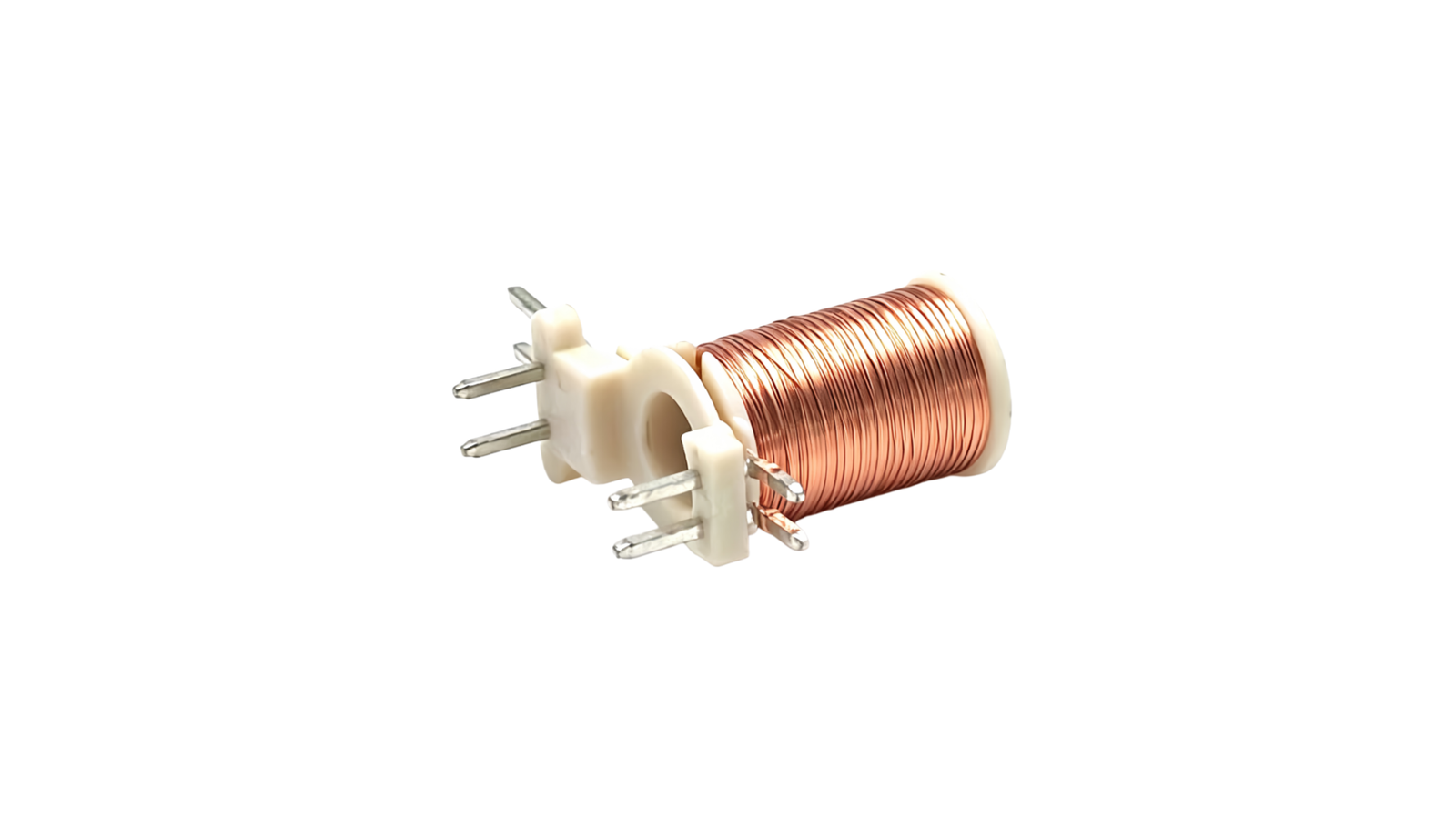
High performance solenoids work by converting electrical energy into controlled linear motion. Current energizes a coil, the coil creates magnetic flux, the magnetic circuit concentrates that flux, and the resulting magnetic force moves an armature against spring force, friction, mechanical load, or fluid pressure.
The basic operating chain is Electrical Input → Coil → Magnetic Flux → Air-Gap Force → Armature Motion → Mechanical Output. The coil creates magnetic excitation, but usable force depends on the complete magnetic circuit, the air gap, the moving assembly, and the real load that the actuator must overcome.

I avoid treating solenoid operation as a pure coil-winding topic. The winding matters, but the final actuator performance depends on electrical, magnetic, and mechanical design working together.
Step 1: Current Energizes the Coil
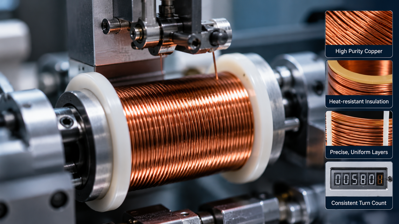
When current flows through the copper winding, it creates a magnetic field. The level of magnetic excitation is influenced by several factors:
- Current through the coil
- Number of winding turns
- Coil geometry
- Available winding volume
- Electrical resistance
- Applied voltage and driver behavior
For a DC solenoid, voltage and coil resistance influence current. As the coil temperature rises, resistance generally rises as well.[^3] That change can reduce current under a fixed-voltage supply and affect magnetic margin.
Step 2: The Magnetic Circuit Concentrates Flux
The core, yoke, pole piece, armature, and related steel components form the magnetic path. Their geometry determines how efficiently the actuator directs flux across the air gap.
The coil creates excitation, but usable force depends on the complete magnetic circuit.
Air gaps matter because magnetic reluctance rises sharply as the gap increases.[^4] This is one reason that solenoid force is normally higher near the end of travel than at the start. A supplier should therefore provide or develop a force-stroke curve rather than relying on one force value.
Step 3: Magnetic Force Moves the Armature
Magnetic force pulls the armature toward a lower-reluctance position. The actuator must overcome all opposing forces, which may include:
- Return spring force
- Friction in guides or bushings
- Mechanical load
- Seal resistance
- Fluid pressure, where applicable
- Misalignment or side load
- Inertia of the moving mechanism
A fast acting solenoid must not only develop enough force. It must develop that force quickly enough to move the armature under real conditions.
Step 4: The Solenoid Releases or Holds Position
The actuator can hold its energized position, release with a spring, release through an external mechanism, or use a latching arrangement depending on the design. Some applications also use peak-and-hold drive strategies. These apply higher initial energy for pull-in, then reduce holding current after the armature has seated.[^5]
That approach can be useful when the application needs strong initial actuation but must control steady-state heating. However, I recommend evaluating the full electrical architecture with the solenoid supplier because driver behavior, wiring, supply tolerance, and control timing all affect actual performance.
What Makes High Performance Solenoids Different?
High performance solenoids differ from basic designs because they are engineered around an application-specific balance of force, size, response, temperature, power, durability, and environmental stability. No single material or maximum number creates high performance. The design must meet several constraints at once with acceptable margin.
A high-performance solenoid should produce useful force across its required stroke, respond consistently under real load, remain within thermal limits at its duty cycle, fit the available package, and maintain function throughout its defined operating environment and service-life target. Trade-offs are unavoidable, so validation is essential.

In supplier evaluations, I look for evidence that the manufacturer understands these trade-offs. A good engineering discussion starts with the required output and operating conditions, not with a generic promise of “higher power.”
1. High Force-to-Size Ratio
A high force-to-size ratio means the actuator provides useful force within the space available in the product. It does not mean that the smallest solenoid is always the best design.
Force capability can be influenced by:
- Ampere-turns
- Air gap and required stroke
- Core and armature geometry
- Magnetic material properties
- Magnetic saturation limits
- Available winding volume
- Heat dissipation through the housing and mounting structure
A compact solenoid may be appropriate for a restricted appliance enclosure, but a smaller frame can reduce thermal headroom. I recommend defining maximum diameter, length, mounting interface, mass, and surrounding clearance before comparing force claims.
2. Fast and Repeatable Response
Solenoid response time is not determined by the coil alone.[^6] Pull-in time and release time can change with:
- Armature mass
- Stroke length
- Spring force
- Friction
- Applied voltage
- Driver circuit
- Magnetic force profile
- Temperature
- Mechanical load
Fast response is only valuable if it remains repeatable under real load and operating temperature. A response-time claim should therefore state the test voltage, load, stroke, ambient temperature, and measurement method.
3. Thermal Performance and Duty Cycle
Electrical power becomes heat.[^7] As a coil heats, winding resistance changes. That can alter current and reduce available magnetic margin in a voltage-driven system. The duty cycle determines whether the heat can dissipate between activations.[^8]
A solenoid with strong cold-state force but unreliable hot-state pull-in is not high performance for that application. I recommend that buyers define:
- Maximum ON time
- Minimum OFF time
- Switching frequency
- Ambient temperature
- Enclosure conditions
- Nearby heat sources
- Permitted coil or housing temperature
Continuous duty is not automatically better than intermittent duty. The correct duty rating depends on the actual operating profile.
4. Power Density and Electrical Efficiency
High performance does not automatically mean low power. Electrical input should be evaluated relative to useful mechanical output, package size, duty cycle, and thermal limits.
Different projects can prioritize different outcomes:
- Maximum force for a short pulse
- Low holding power
- Compact size
- Fast pull-in
- Limited current draw
- Reduced temperature rise
A high power solenoid may be suitable in one application and impractical in another. The correct comparison is not wattage alone. It is whether the electrical input produces the required mechanical result within the system’s thermal and power constraints.
5. Mechanical Durability and Service Life
A coil can be electrically sound while the overall solenoid fails mechanically. Service life can be influenced by armature guidance, alignment, impact at end of stroke, spring fatigue, surface wear, contamination, mounting rigidity, and switching frequency.[^9]
Cycle-life claims only have meaning when the test conditions are defined. I ask for the following details before treating a life claim as comparable:
- Stroke length
- Mechanical load
- Cycle frequency
- Coil temperature or ambient temperature
- Mounting orientation
- Electrical drive profile
- Acceptable performance degradation
- Failure criteria
6. Environmental Stability
A solenoid that performs well on a room-temperature test bench may not perform acceptably in an enclosed product exposed to vibration, moisture, dust, chemical vapor, or temperature variation.
Environmental requirements can affect material selection, sealing approach, insulation system, surface treatment, tolerance choices, and test plan.[^10] Buyers should specify the expected conditions early, not after a prototype is complete.
| Misleading Shortcut | Better Engineering Question |
|---|---|
| Highest force | Required force at what stroke? |
| Fastest response | At what voltage, load, and temperature? |
| 100% duty | Is continuous duty actually required? |
| Highest wattage | What force and thermal margin does that power produce? |
| Highest insulation class | Can the complete assembly survive and still actuate? |
| Smallest size | Does it still meet force, heat, and life requirements? |
| Millions of cycles | Under what load, stroke, and test conditions? |
A high-performance solenoid is not the design with the highest specification in one column. It is the design that meets the required combination of force, stroke, speed, temperature, duty, size, and life with sufficient margin.
How Should You Evaluate High Performance Solenoids?
You should evaluate high performance solenoids through documented tests that reproduce the application’s electrical, thermal, mechanical, and environmental conditions. A nominal force rating or room-temperature demonstration is not enough. The most valuable evidence shows whether the actuator still performs at minimum voltage, maximum load, and stabilized operating temperature.
The essential evaluation process includes force versus stroke measurement, pull-in and holding-force checks, response-time tests, duty-cycle thermal testing, voltage-range verification, cycle-life testing, and environmental assessment. Every result should include the conditions under which it was measured, because those conditions determine whether the data is relevant.

I recommend building the validation plan around the real failure risks of the product. For many designs, the critical condition is not nominal voltage at room temperature. It is a hot coil, minimum supply voltage, maximum mechanical load, and the required operating frequency.
Start With the Force-Stroke Curve
A maximum-force statement such as “100 N” does not answer the most important question: 100 N at what stroke or air gap?
A solenoid force-stroke curve shows the usable force available at different armature positions.[^11] It helps engineers determine whether the actuator can initiate movement at the largest gap and maintain sufficient force through the motion.
Separate Pull-In Force From Holding Force
Pull-in force is the force available when the armature starts from its initial position. It must overcome spring force, friction, pressure, and mechanical resistance at the beginning of the movement.
Holding force applies when the armature is seated or close to its final position. Holding force can be much higher than pull-in force in many configurations.[^12]
Procurement teams should avoid comparing these values as though they are interchangeable.
Test Response Time Under Defined Conditions
Response time should distinguish between:
- Pull-in time: the time from energization to the required actuation position.
- Release time: the time from de-energization to return or release.
The test should define voltage, load, stroke, temperature, mounting, and measurement threshold. A fast response under no load can be irrelevant if the production mechanism introduces friction or opposing force.
Verify Thermal and Voltage Margin
The key validation point is often:
Hot coil + minimum supply voltage + maximum mechanical load
This combined condition checks whether thermal effects and electrical tolerance reduce magnetic force enough to cause inconsistent actuation. It is more representative than testing only at nominal voltage with a cold actuator.
| Test | Why It Matters |
|---|---|
| Force vs. stroke | Shows usable force across movement |
| Minimum-voltage pull-in | Verifies magnetic margin |
| Hot-state pull-in | Verifies thermal and magnetic margin |
| Response time | Confirms switching requirement |
| Duty-cycle thermal test | Verifies temperature rise |
| Cycle-life test | Verifies durability under stated conditions |
| Environmental test | Confirms real operating capability |
| Current/power measurement | Connects electrical input to mechanical output |
Review Supplier Evidence Carefully
For a customized project, I recommend requesting a controlled documentation package that may include:
- Product drawing and revision history
- Force-stroke test conditions and results
- Electrical resistance and current specifications
- Response-time test method
- Thermal test profile
- Life-test method and failure criteria
- Material declarations where required
- Compliance certificates or declarations applicable to the part
SolenElec states that it uses incoming material inspection, process controls, outgoing inspection, and MES-based traceability in its manufacturing system. Buyers should verify the relevant quality records, inspection scope, and applicable certification documents for the particular product and order. Certifications and compliance statements should always be reviewed as documents, not assumed from a general supplier profile.
How Do You Choose a High-Performance Solenoid for Your Application?
You choose a high-performance solenoid by defining the motion, force across the stroke, response time, available space, electrical architecture, duty cycle, environment, and required life before selecting a part. This process prevents a supplier from optimizing the wrong parameter and helps teams compare designs on the same basis.
The best selection process starts with the application requirement, not a catalog force rating. Define what must move, how far it must move, how quickly it must move, how often it must operate, and under what voltage and temperature conditions. Then validate the solenoid under the worst relevant operating condition.

I have seen specification reviews become much more productive when the team replaces vague requirements such as “high force” or “long life” with measurable conditions. Those details allow engineering teams to identify realistic trade-offs early.
Step 1: Define the Required Motion
Start with the mechanism:
- Is the motion pull, push, or both?
- What stroke is required?
- Is the movement linear?
- Does the application require a spring return, external return, or latching mechanism?
- Does the armature need to hold a position after travel?
The motion defines the basic actuator architecture.
Step 2: Define Force Across the Stroke
Do not specify only “100 N required.” Define the force requirement by position.
For example, the mechanism may need its highest force at the beginning of a 5 mm stroke to overcome spring preload or fluid pressure. Another mechanism may require lower initial force but stable holding force at the end position.
A force-stroke requirement is more useful than a single force value because it gives the supplier a clear design target.
Step 3: Define the Response-Time Requirement
“Fast switching” is too vague for supplier selection. A more useful statement is:
- The actuator must pull in within a defined number of milliseconds.
- The actuator must release within a defined number of milliseconds.
- The timing must apply at specified voltage, load, and temperature.
This requirement helps determine whether the design needs changes in armature mass, spring selection, coil configuration, or driver architecture.
Step 4: Define Available Space
Record the installation limits:
- Maximum diameter
- Maximum length
- Mounting geometry
- Weight limit
- Connector clearance
- Nearby components
- Cooling path and enclosure constraints
This is where force-to-size ratio becomes meaningful. A compact solenoid may be necessary, but the team must verify that it can still meet heat, force, and life targets.
Step 5: Define the Electrical Architecture
The electrical system can strongly influence solenoid performance. Specify:
- AC or DC supply
- Nominal voltage
- Supply-voltage tolerance
- Available current
- Current limits
- PWM control, if applicable
- Peak-and-hold drive, if applicable
- Rectifier or control circuit requirements
The solenoid coil and driver should be evaluated as a system. A well-designed coil can still underperform if supply voltage drops or the control method does not provide enough pull-in energy.
Step 6: Define Duty Cycle
Duty cycle details should include:
- Maximum ON time
- Minimum OFF time
- Expected switching frequency
- Operating pattern during peak use
- Required continuous operation, if any
This information determines thermal loading and affects the design margin required for a high duty cycle solenoid.
Step 7: Define Thermal and Environmental Conditions
I recommend specifying the full environment:
- Ambient temperature range
- Enclosure temperature
- Nearby heat sources
- Moisture or condensation risk
- Dust exposure
- Vibration and shock
- Chemical exposure
- Installation orientation
These conditions help the supplier identify materials, coatings, sealing measures, and validation tests appropriate to the project.
Step 8: Define Required Life and Failure Criteria
“Long life” is not an engineering requirement. Instead, define:
- Required number of cycles
- Stroke and mechanical load during testing
- Operating frequency
- Temperature condition
- Permitted change in response time or force
- Electrical failure criteria
- Mechanical failure criteria
Engineering Example: Compact Pneumatic Actuator
Consider a compact pneumatic actuator with these requirements:
- 24 VDC supply
- Limited installation space
- 5 mm stroke
- Defined pull-in force requirement
- Fast response target
- High switching frequency
- 40°C enclosure environment
- Long cycle-life target
The wrong selection method would be simple: choose the smallest solenoid with the highest listed force.
The correct selection logic is:
Force-stroke requirement → Available space → Voltage/current → Response time → Duty cycle → Thermal condition → Life requirement → Hot-state validation
The team should first confirm the force needed at the initial 5 mm air gap, not only the holding force at the end of travel. Next, it should assess whether the available winding volume can deliver the required pull-in force without exceeding the thermal limits of the enclosure.
Then, the team should test the actuator at low supply voltage, with the maximum expected load, after it reaches operating temperature. If response time or pull-in performance becomes inconsistent under that condition, the solenoid is not suitable even if its room-temperature catalog force appears impressive.
High performance means meeting all of these constraints together, not maximizing a single parameter.
For an OEM project, I recommend involving a qualified solenoid engineer early. SolenElec offers OEM and ODM support for coil and actuator customization, including engineering input on coil design, materials, and tooling. The final selection should still be based on application-specific testing and documented acceptance criteria.
Frequently Asked Questions
What is a high-performance solenoid?
A high-performance solenoid is an electromagnetic actuator that meets demanding requirements for force, stroke, response time, duty cycle, temperature, package size, repeatability, environmental resistance, and service life. It is not defined by maximum force or wattage alone. Its performance must be proven under the conditions of the intended application.
What makes a solenoid more powerful?
A solenoid can produce more magnetic force through changes in current, coil turns, winding volume, magnetic circuit design, air-gap geometry, and core materials. However, more force may increase heat, size, current demand, or mechanical stress. I recommend evaluating usable force across the required stroke rather than only maximum force.
Does a stronger solenoid require more power?
Not always, but greater force often requires more electrical input, more winding volume, a better magnetic circuit, or a reduced air gap. The correct question is whether the solenoid delivers the required mechanical output within the application’s space, thermal, voltage, and duty-cycle limits. Higher wattage alone does not guarantee better performance.
How does stroke affect solenoid force?
Stroke affects the air gap between magnetic components. In many solenoid designs, force decreases as the air gap increases. This means pull-in force at the start of movement can be much lower than holding force when the armature is seated. A force-stroke curve is therefore essential for selecting a solenoid correctly.
How do you test a high-performance solenoid?
Testing should include force versus stroke, minimum-voltage pull-in, hot-state pull-in, pull-in and release time, duty-cycle thermal behavior, current or power measurement, cycle-life testing, and relevant environmental testing. Each test should define voltage, load, stroke, temperature, mounting, frequency, and pass/fail criteria so the results are meaningful.
Conclusion
Do not define high performance solenoids by maximum force, wattage, or speed alone. I recommend defining the required force across the stroke, response time, available space, duty cycle, temperature range, electrical limits, environmental conditions, and service-life target first. Then verify that the solenoid meets those requirements under real operating conditions, especially hot-state and minimum-voltage conditions. For OEM projects, SolenElec can support customized solenoid and coil development, but buyers should begin with a clear validation specification and review supplier test evidence before approving production.