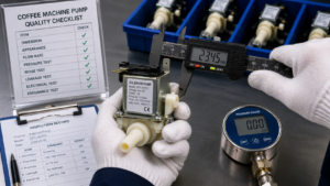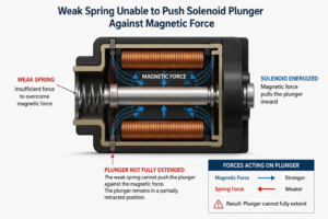
Premature coil failures can disrupt production lines and damage a brand's reputation for quality. Many teams find their solenoid coils overheat, fail under environmental stress, or underperform, leading to costly warranty claims and a loss of customer trust. To solve this, a holistic design approach is necessary, balancing electrical, magnetic, and thermal demands1 from the very beginning.
To properly design a coil for performance and reliability, you must start by defining the application's requirements, not by choosing a wire gauge. This involves a systematic process of balancing electrical performance, magnetic force, heat dissipation, material selection, structural integrity, and environmental resistance to create a component that is not only effective but also manufacturable at scale.

Now that you have the direct answer, you might be wondering what this systematic process looks like in practice. It's about making a series of informed trade-offs. In the sections below, we'll break down each critical stage, from defining your needs to final validation.
What Application Requirements Should Be Defined Before Coil Design Begins?
Trying to design a coil by first picking a wire gauge is like building a house by first choosing the paint color. It ignores the foundation. If the application's real-world operating conditions are not defined upfront, the final product is destined for failure.
The first step is to create a detailed list of all system-level requirements. This includes the required force, stroke, operating voltage, duty cycle, and the physical space constraints2. Only with this complete picture can you begin to make informed design choices.
Key Design Considerations
A high-performance coil is a product of its environment. Before a single specification is written, we must understand the world it will live in. Over my 20 years in OEM manufacturing, I've seen countless projects saved by spending more time in this initial discovery phase.
Key requirements to define include:
- Electrical Parameters: What is the available input voltage and maximum current? Is the power source AC or DC? This dictates the coil's basic electrical properties, such as resistance and impedance.
- Mechanical Performance: What is the required magnetic force or torque? What is the necessary stroke length for the solenoid's plunger? These factors directly influence the coil's size, number of turns, and magnetic circuit design.
- Duty Cycle: Will the coil be energized continuously (100% duty cycle) or intermittently? A continuously powered coil generates constant heat and requires a more robust thermal management strategy.3 An intermittent coil might handle higher peak power but needs to be designed to avoid overheating during its "on" time.
- Environmental Conditions: What is the expected ambient temperature range? Will the coil be exposed to moisture, humidity, chemicals, vibration, or mechanical shock? These factors are critical for selecting insulation materials, encapsulation methods (like potting or overmolding), and housing.
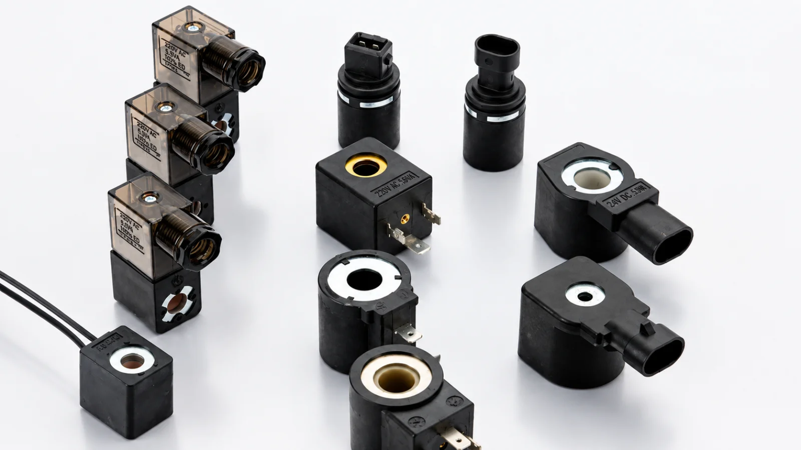
- Physical Constraints: What is the maximum allowable size and weight? Are there specific mounting requirements or connector types needed? These constraints often create the most significant design challenges, forcing compromises between size and power.
By documenting these requirements first, we create a blueprint for success. This prevents the common mistake of, for example, increasing winding turns to boost magnetic force, only to find the coil overheats because the increased electrical resistance and reduced cooling space were not accounted for. Starting with a complete understanding of the application ensures that every subsequent decision is made to achieve a balanced, reliable, and effective final product.
How Do Conductor and Insulation Materials Affect Coil Performance?
Selecting the right materials feels like a simple choice, but it has profound consequences for the coil's efficiency, lifespan, and cost. Using a low-grade conductor or inadequate insulation can lead to overheating, short circuits, and premature failure, even if the geometry is perfect.
The choice of conductor material directly impacts electrical resistance and cost, while the insulation system determines the coil's maximum operating temperature and its resistance to environmental factors. These two elements must be chosen in harmony to meet the application's demands.

Material Selection Guide
The heart of any coil is its conductor and insulation. Their properties are intertwined and directly influence the final performance. Let's break down the key considerations for each.
Conductor Material Selection
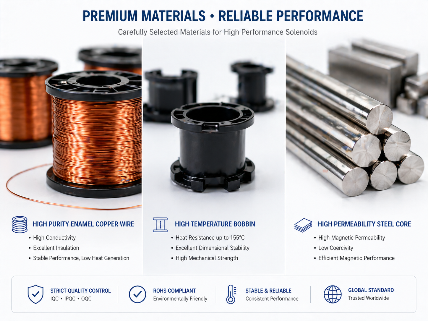
For most high-performance applications, copper is the conductor of choice. Its high electrical conductivity means less energy is lost as heat for a given current.4
| Feature | Copper (Cu) | Aluminum (Al) |
|---|---|---|
| Conductivity | High (100% IACS) | Moderate (61% IACS) |
| Resistance | Low | Higher than Copper |
| Weight | Heavier | Lighter |
| Cost | Higher | Lower |
| Corrosion | Good resistance | Prone to oxidation |
| Best For | High-efficiency, space-constrained applications | Weight-sensitive or cost-driven applications |
While aluminum is lighter and cheaper, its lower conductivity means a larger wire diameter is needed to carry the same current as copper5, which can be a problem in space-constrained designs. We almost always recommend high-purity copper wire to ensure maximum efficiency and a smaller product footprint.
Insulation System and Thermal Class6
The insulation is the unsung hero of coil reliability. It prevents short circuits between windings and determines the coil's maximum safe operating temperature. Insulation systems are rated by "Thermal Class," which indicates the temperature they can withstand continuously for 20,000 hours.
- Class A (105°C): Basic, for low-power applications.
- Class B (130°C): Common in home appliances.
- Class F (155°C): A standard for industrial and automotive solenoids.
- Class H (180°C): For high-temperature applications, high-reliability applications.
- Class N/R (200°C/220°C): Used in extreme environments.
When we design a coil, we always select an insulation class that provides a significant safety margin above the calculated maximum operating temperature. This is one of the most critical factors for long-term reliability, as heat is the primary cause of insulation degradation and, ultimately, coil failure7. We also ensure all materials, from the plastic bobbin to the encapsulation resin, meet or exceed the chosen thermal class.
How Do Winding Geometry and Magnetic Design Influence Efficiency?
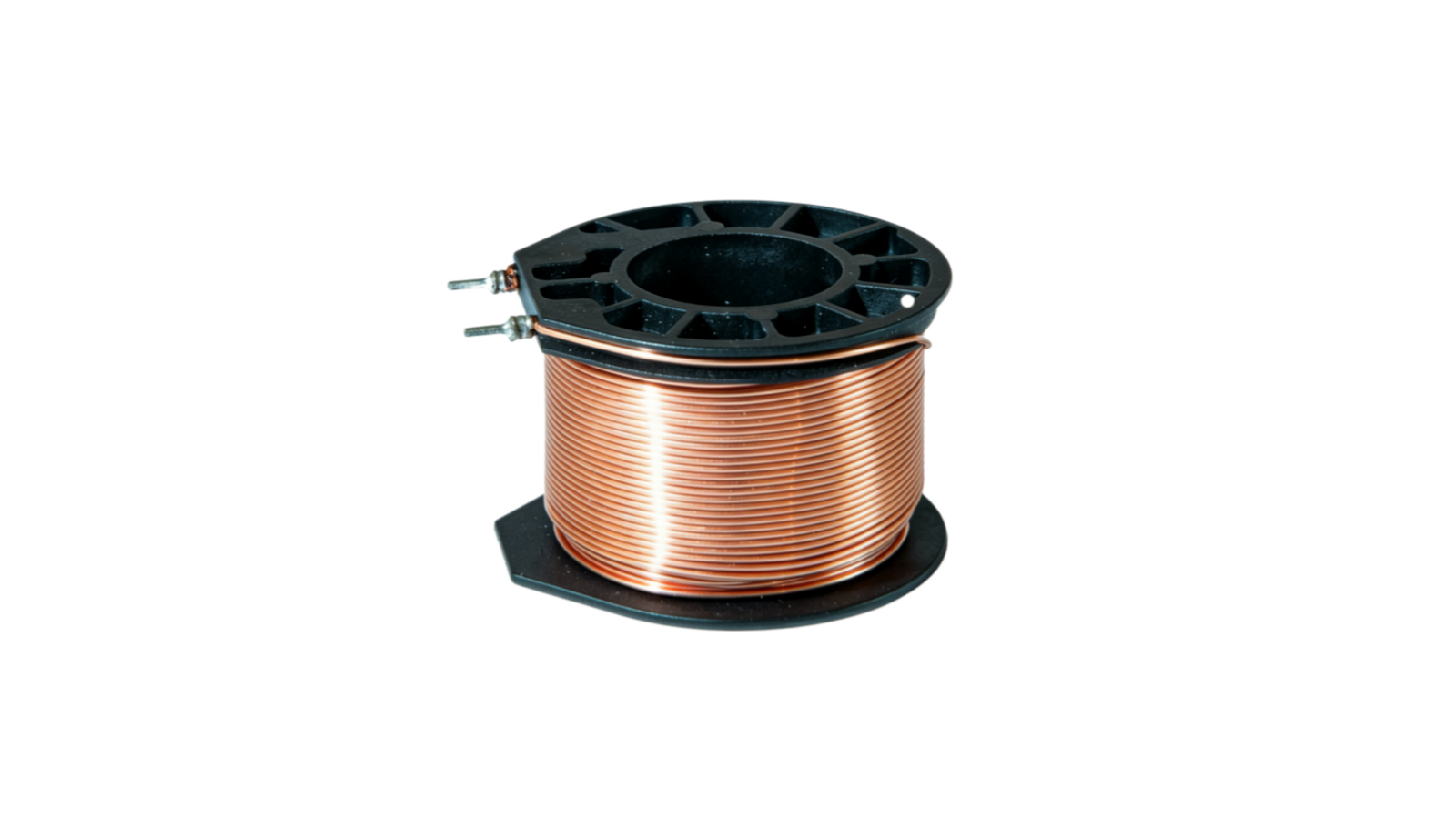
Optimizing a coil isn't just about cramming in as much wire as possible. The way the wire is wound and how it interacts with the magnetic core directly impacts efficiency. A poorly designed winding can create a weak magnetic field and generate excessive heat, wasting energy.
The goal is to maximize the magnetic field generated for a given amount of electrical power. This is achieved by carefully controlling the number of turns, wire diameter, winding pattern, and the design of the surrounding magnetic circuit (the core and housing).
Engineering Insights
The relationship between winding geometry and magnetic efficiency is a delicate balancing act. More turns create a stronger magnetic field, but they also increase the coil's length, resistance, and heat generation. This is where expertise in physics and manufacturing comes into play.
The Ampere-Turns Trade-Off
The strength of an electromagnet is defined by its "ampere-turns8" (AT)—the product of the current flowing through the coil (Amps) and the number of wire turns (N). You can achieve the same magnetic force with:
- High current and few turns: This requires a thick wire (to handle the current) but results in a low-resistance, low-voltage coil.
- Low current and many turns: This allows for a thin wire but results in a high-resistance, high-voltage coil.
The choice depends on the available power supply. However, simply adding more turns is a common mistake. More turns mean a longer wire, which increases resistance (R). Since power loss (heat) is proportional to I²R9, this can lead to a runaway temperature problem, especially if the winding becomes so dense that it traps heat. A successful design a coil project requires calculating the optimal balance to achieve the target ampere-turns without exceeding the thermal budget.
Winding Pattern and Fill Factor
The "fill factor" is the percentage of the available winding area that is actually filled with copper. A higher fill factor generally leads to a more powerful and efficient coil.10
- Scramble (or "wild") Winding: Fast and cheap to produce, but results in a low fill factor (around 70-80%). The random wire placement leaves air gaps that trap heat and reduce magnetic efficiency.
- Layer (or "perfect") Winding: Each turn is laid precisely next to the previous one in neat layers. This method achieves a much higher fill factor (often >90%), resulting in a more compact, powerful, and thermally efficient coil. It is more complex and slower to produce but is essential for high-performance applications.
At SolenElec, we use automated, precision winding machines that enable us to achieve high fill factors consistently, ensuring every coil we produce delivers the maximum possible performance for its size.
How Can Thermal and Environmental Failures Be Prevented?
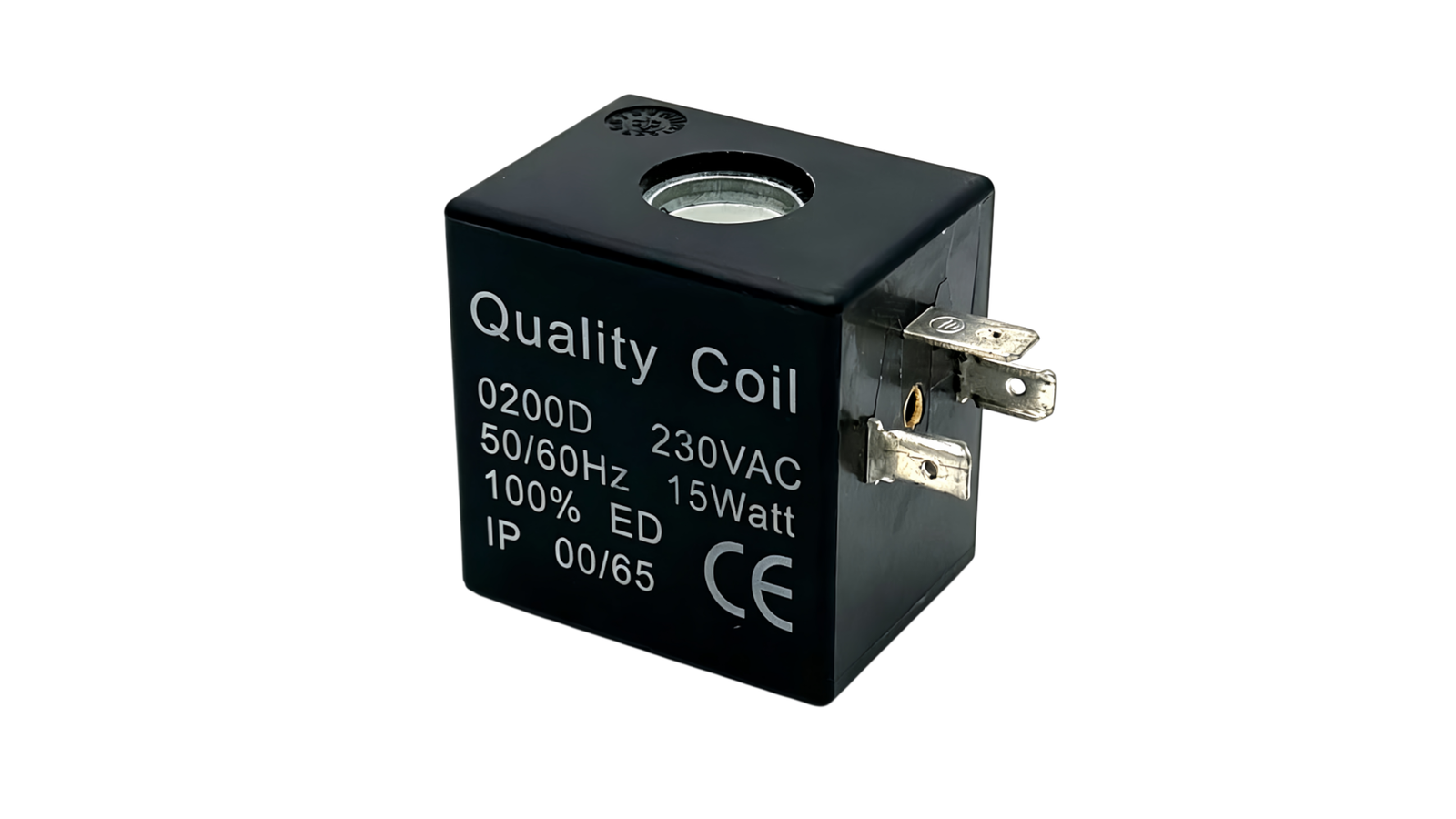
A coil can have perfect electrical and magnetic properties on paper, but if it can't survive its operating environment, it is a failure. Heat is the number one enemy of coil longevity, and exposure to moisture, chemicals, or vibration can cause rapid degradation.
Preventing these failures requires a two-pronged strategy: robust thermal management to dissipate heat effectively and physical protection to shield the coil from external hazards. This involves careful material selection and encapsulation techniques.
Improving Reliability
Designing for durability is non-negotiable, especially for brands whose reputation rests on reliability. In my experience, focusing intensely on thermal and environmental protection during the design phase is what separates an average coil from a great one. This is a core part of how we design a coil for our leading home appliance partners.
Mastering Thermal Management
Every energized coil generates heat (Joule heating).11 The design must ensure this heat can escape faster than it builds up, keeping the coil's temperature below its insulation class limit.
Key strategies include:
- Optimizing Conductor Size: Using a wire gauge that is large enough for the current minimizes resistive heat generation (I²R losses) from the start.
- Maximizing Surface Area: A coil with more exposed surface area can dissipate heat more effectively into the surrounding air or mounting structure.
- Using Thermally Conductive Materials: Selecting bobbin plastics and encapsulation compounds (like epoxy or polyurethane resins) with high thermal conductivity helps transfer heat from the inner windings to the outer surface.
- Ensuring Airflow: In the final application, ensuring the coil has access to airflow, even if passive, can dramatically lower its operating temperature.
- Considering the Heat Sink: The metal frame or valve body the coil is mounted on often acts as a heat sink. The design must ensure good thermal contact between the coil and this structure.
Shielding Against Environmental Hazards
For appliances operating in kitchens, bathrooms, or industrial settings, physical protection is just as critical as thermal management.
- Moisture and Chemical Protection: The best defense is encapsulation, also known as "potting." The entire coil assembly is placed in a housing and filled with a liquid resin that cures to form a solid, void-free block. This completely seals the windings from moisture and corrosive agents. We select resins based on the specific chemicals the coil might encounter.
- Vibration and Shock Resistance: Potting also provides excellent mechanical support, locking the windings in place and preventing them from vibrating12, which could lead to abrasion and insulation failure. For extreme vibration environments, we use flexible polyurethane resins that can absorb mechanical energy.
- Sealing and IP Ratings: For products requiring a specific Ingress Protection (IP) rating (e.g., IP65 or IP67 for water resistance), we design the coil housing, lead wire exit, and connector interface to form a complete, validated seal.
By combining these thermal and environmental strategies, we build coils that don't just perform well on day one—they perform reliably for years, even in the harshest conditions.
Why Must Manufacturability, Testing and Validation Be Considered Early?
A brilliant prototype that cannot be mass-produced consistently and economically is useless. Thinking about the manufacturing process and testing requirements from day one is critical. Ignoring this leads to production delays, quality control nightmares, and higher costs.
A design is only complete when it includes a clear plan for production, assembly, and validation. This "Design for Manufacturability" (DFM) approach ensures that tolerances, winding techniques, and testing procedures are built into the coil's DNA, not added as an afterthought.
From Design to Mass Production
I've seen engineers present a "perfect" coil prototype that was hand-wound and assembled with extreme precision. The problem? Our automated production lines couldn't replicate it. The project had to go back to the drawing board, costing weeks of time. This is why manufacturability, testing, and validation are not the final step; they are an integral part of the entire design process.
Design for Manufacturability (DFM)
When we design a coil, our engineering team works alongside our production staff. This concurrent engineering approach ensures every design choice is compatible with our high-volume manufacturing capabilities.
Key DFM considerations include:
- Winding Process: Can the chosen wire gauge and winding pattern be executed reliably by our automated winders? Are the bobbin flanges designed to support the wire and prevent slips?
- Tolerances: Are the specified dimensional and electrical tolerances achievable in mass production? Overly tight tolerances can lead to high scrap rates and drive up costs.
- Lead Wire & Termination: How will the coil's fine magnet wire be connected to the external lead wires or terminals? This connection point is a common point of failure. The design must allow for a robust, automated soldering or welding process.
- Assembly: How does the coil fit into the final solenoid assembly? The design must account for assembly line ergonomics and speed.
A Rigorous Testing and Validation Protocol
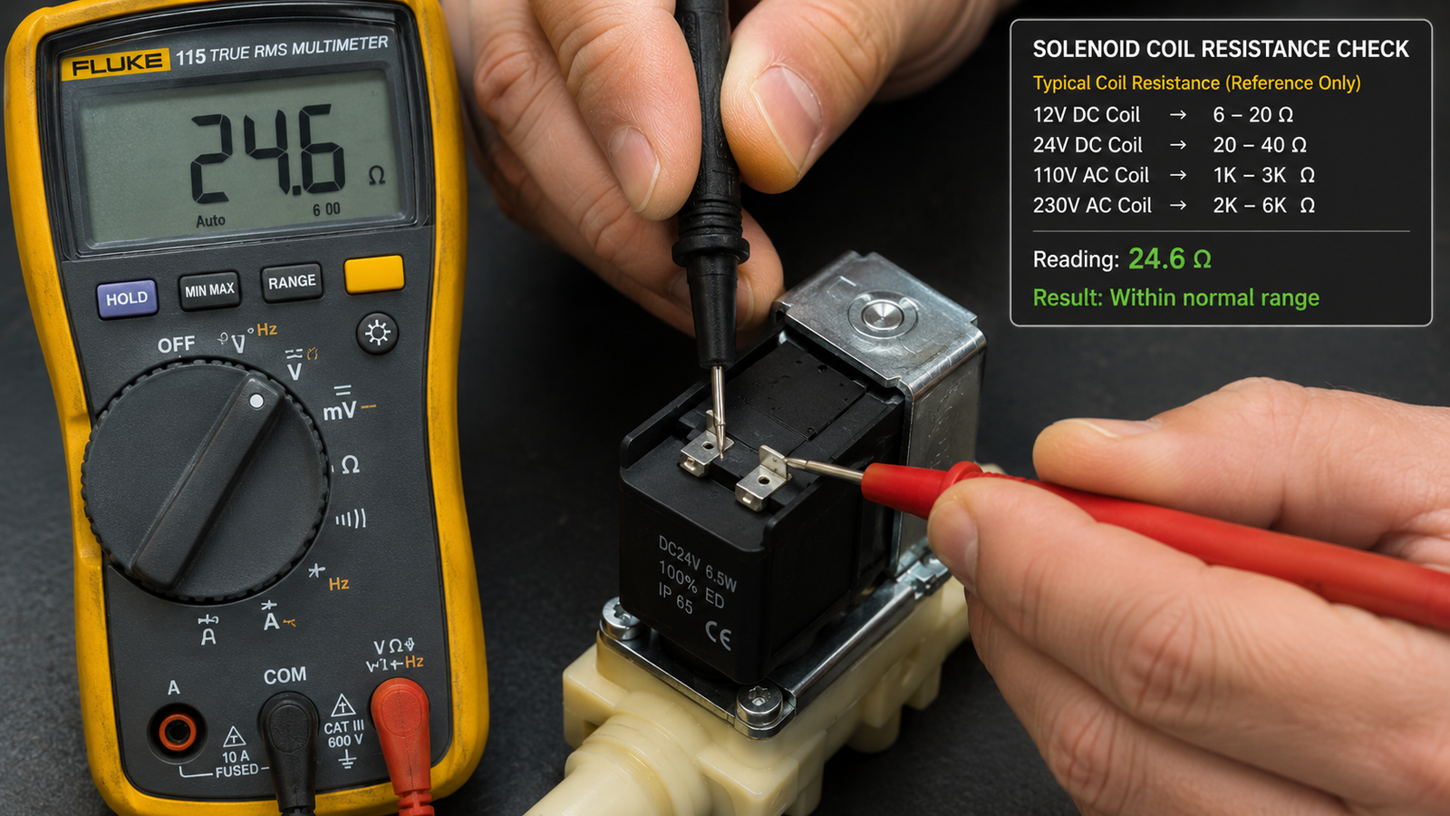
A design isn't proven until it passes a battery of tests that simulate its entire life cycle. Our validation process goes far beyond a simple resistance check.
Our standard validation includes:
- Electrical Tests:
- Resistance & Inductance: Verifies the winding is correct.
- Hi-Pot (Dielectric Strength): Tests the insulation's ability to withstand high voltage without breaking down.
- Performance Tests:
- Force/Stroke Measurement: Confirms the coil produces the required mechanical output.
- Thermal Rise Test: The coil is run at full load to ensure its temperature stabilizes below the design limit.
- Reliability & Environmental Tests:
- Thermal Cycling: The coil is subjected to extreme temperature swings for hundreds or thousands of cycles to test for material fatigue.
- Vibration & Shock Testing: Simulates transportation and operational stresses.
- Salt Spray / Humidity Test: Simulates corrosive or damp environments.
By integrating these DFM and validation principles early, we prevent costly surprises and ensure that the coil we design is the same high-quality coil we deliver by the thousands.
Frequently Asked Questions
What is the most common cause of solenoid coil failure?
The most common cause is overheating. This happens when the coil's temperature exceeds the thermal rating of its insulation, causing the insulation to become brittle and break down. This can be caused by excessive voltage, an incorrect duty cycle, or poor heat dissipation in the final application.
How does duty cycle affect coil design?
Duty cycle is critical. A 100% duty cycle (continuously on) coil must be designed to dissipate heat constantly and will typically have higher resistance and operate at a lower power level. An intermittent duty cycle coil can handle higher power for short bursts but will overheat if left on too long.
What is the difference between potting and overmolding?
Both are encapsulation methods. Potting involves placing the coil in a housing and filling it with resin. Overmolding is an injection molding process where a thermoplastic material is molded directly over the coil, forming a sealed, durable outer shell. Overmolding is often faster for high-volume production and can create more complex shapes.
Why is copper preferred over aluminum for most coil windings?
Copper is preferred due to its superior electrical conductivity. For a given size, a copper wire has lower resistance than an aluminum one, meaning it generates less waste heat and is more efficient. While aluminum is lighter and cheaper, it requires a larger wire diameter to achieve the same performance, which is often not feasible in compact designs.
Conclusion
Successfully designing a coil is not a simple task of winding wire around a bobbin; it is a comprehensive engineering exercise. It requires a delicate balance between electrical performance, magnetic force, thermal management, material science, and manufacturability. By starting with a deep understanding of the application requirements and systematically addressing each of these areas, you can develop a coil that delivers exceptional performance and long-term reliability. This holistic approach prevents common failures, reduces warranty costs, and ultimately protects your brand's reputation.
With over 20 years of OEM/ODM experience, we specialize in this integrated approach. If you are a purchasing or brand manager looking for a reliable partner to develop custom solenoid coils for your appliance brand, we can help.
Contact SolenElec today to discuss your project and discover how our expertise in coil design and manufacturing can enhance your products.
"Recent Design and Application Advances in Micro-Electro ... - PMC", https://pmc.ncbi.nlm.nih.gov/articles/PMC12194837/. Engineering studies of electromagnetic actuators describe coil performance as a coupled electromagnetic-thermal problem, supporting the need to balance electrical input, magnetic force generation, and heat dissipation in solenoid design. Evidence role: expert_consensus; source type: paper. Supports: A peer-reviewed engineering source should support that solenoid or electromagnetic actuator performance and reliability depend on coupled electromagnetic, electrical, and thermal design constraints.. Scope note: This would support the general design principle, not the specific manufacturing process used by the article's author. ↩
"Linear actuator", https://en.wikipedia.org/wiki/Linear_actuator. University-level actuator design materials identify mechanical output requirements, available electrical supply, duty cycle, and packaging constraints as primary inputs in sizing and evaluating solenoid actuators. Evidence role: general_support; source type: education. Supports: An educational or engineering design source should identify force, stroke, supply voltage, duty cycle, and dimensional limits as fundamental inputs for solenoid actuator design.. Scope note: Such a source would validate the requirement categories generally, not the completeness of this article's checklist for every application. ↩
"Design and Application of Joule Heating Processes for ... - PMC", https://pmc.ncbi.nlm.nih.gov/articles/PMC11565571/. Electrical engineering references on coil duty cycle explain that resistive heating occurs during energization and that continuous-duty coils must dissipate heat at the average power level for sustained operation. Evidence role: mechanism; source type: education. Supports: The source should explain that resistive heating occurs while current flows and that higher duty cycle increases average power dissipation and temperature rise.. ↩
"Properties of copper and copper alloys at cryogenic temperatures", https://nvlpubs.nist.gov/nistpubs/Legacy/MONO/nistmonograph177.pdf. Standard electrical-property references list copper among the highest-conductivity engineering metals, which supports its use in windings where lower resistance reduces I²R heat losses for a given conductor size. Evidence role: mechanism; source type: institution. Supports: A neutral materials or electrical reference should support copper's high conductivity and the resulting lower resistance-related heating compared with lower-conductivity conductors of the same geometry.. ↩
"Electrical resistivity and conductivity", https://en.wikipedia.org/wiki/Electrical_resistivity_and_conductivity. Conductor-property references report aluminum at roughly three-fifths of copper's electrical conductivity, implying that an aluminum conductor must use a larger cross-sectional area to approach copper's resistance for the same length. Evidence role: mechanism; source type: institution. Supports: The source should show that aluminum's conductivity is substantially lower than copper's and that equivalent resistance requires a larger aluminum cross-section.. ↩
"Insulation system", https://en.wikipedia.org/wiki/Insulation_system. Electrical insulation standards such as IEC 60085 classify insulation systems by thermal endurance, linking classes including 105°C, 130°C, 155°C, and 180°C to long-term operation under specified aging assumptions. Evidence role: definition; source type: institution. Supports: A standards body or technical institution should define insulation thermal classes and their relationship to continuous operating temperature and expected insulation endurance.. Scope note: The standard supports the classification framework; actual coil life also depends on voltage stress, environment, construction quality, and thermal cycling. ↩
"Degradation Monitoring of Insulation Systems Used in Low ...", https://pmc.ncbi.nlm.nih.gov/articles/PMC7374401/. Studies of electrical insulation aging show that elevated temperature accelerates chemical and mechanical degradation of insulation materials, making thermal stress a major contributor to winding insulation failure. Evidence role: mechanism; source type: paper. Supports: A peer-reviewed source should explain that elevated temperature accelerates degradation of electrical insulation materials and reduces insulation life.. Scope note: The source would support heat as a major mechanism, while individual field failures may also involve moisture, contamination, mechanical stress, or overvoltage. ↩
"Ampere-turn", https://en.wikipedia.org/wiki/Ampere-turn. Electromagnetism references define the ampere-turn as the product of current and the number of turns in a winding, a quantity used to express magnetomotive force in magnetic circuits. Evidence role: definition; source type: encyclopedia. Supports: The source should define ampere-turns as current multiplied by winding turns and relate it to magnetomotive force.. ↩
"Joule heating", https://en.wikipedia.org/wiki/Joule_heating. Basic circuit theory states that resistive power dissipation follows Joule's law, P = I²R, which explains why coil current and resistance directly determine heat generation. Evidence role: mechanism; source type: education. Supports: The source should explain Joule heating and the equation P = I²R for resistive power dissipation.. ↩
"Electric motor", https://en.wikipedia.org/wiki/Electric_motor. Research on wound electromagnetic devices shows that higher copper fill factors improve conductor utilization in the winding window and can reduce resistance or increase ampere-turn capacity within fixed space constraints. Evidence role: general_support; source type: paper. Supports: A research source should support the relationship between higher winding fill factor, copper utilization, resistance, and electromagnetic performance.. Scope note: Many studies address motors or transformers rather than solenoid coils specifically, so the citation would provide contextual support for the electromagnetic design principle. ↩
"Joule heating", https://en.wikipedia.org/wiki/Joule_heating. Physics references describe Joule heating as the conversion of electrical energy into heat when current passes through a resistive conductor, which applies directly to energized coil windings. Evidence role: mechanism; source type: education. Supports: The source should explain that electrical current through resistance converts electrical energy into thermal energy.. ↩
"Potting (electronics)", https://en.wikipedia.org/wiki/Potting_(electronics). Electronics-packaging literature describes potting compounds as encapsulants that mechanically support components, limit relative motion, and help protect assemblies from vibration-induced damage. Evidence role: mechanism; source type: research. Supports: A neutral reliability or electronics-packaging source should support that encapsulants can immobilize components or windings and reduce vibration-induced mechanical stress.. Scope note: The source would support the general mechanical function of potting; effectiveness depends on resin modulus, adhesion, cure quality, geometry, and operating temperature. ↩