Many in the industry believe a hydraulic valve's performance hinges solely on its mechanical body. This view, however, overlooks the true driver of action, often leading to systems with sluggish response times, poor precision, and questionable reliability. The solution lies in understanding that high-performance solenoid coils are essential, converting electrical signals into the precise mechanical force that commands the entire valve1.
A solenoid coil is essential because it is the electromechanical actuator that converts electrical energy into a concentrated magnetic field. This field provides the force needed to move a valve's spool or poppet. In switching valves, they deliver rapid open/close action, while in proportional valves, they enable precise, continuous control over flow and pressure by modulating the magnetic field's strength.2
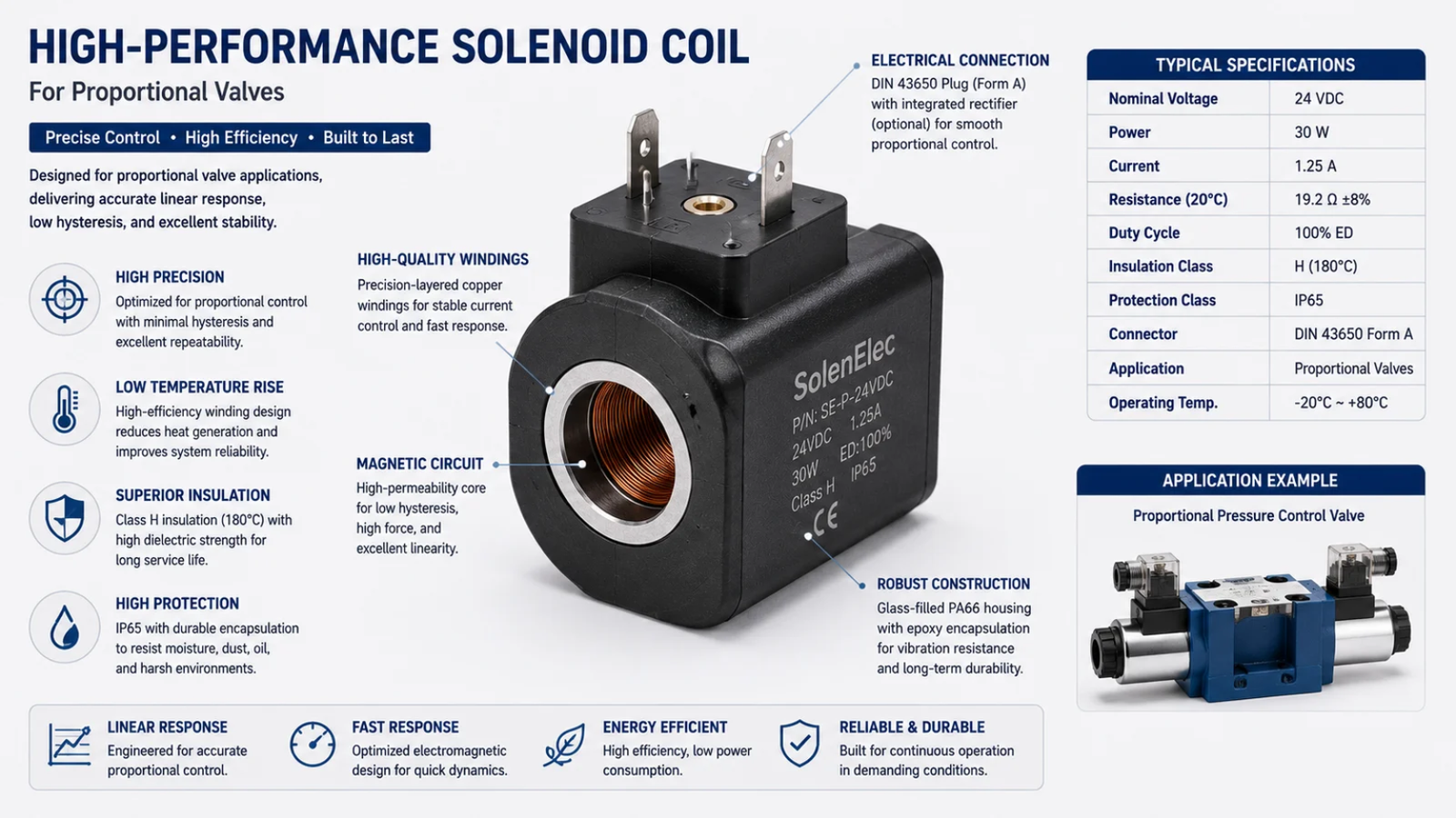
Now that we have established their fundamental importance, it's time to dig deeper. Let's explore exactly what these coils do inside a valve and how their design directly influences the performance, accuracy, and dependability of your entire hydraulic or pneumatic system.
What Does a Solenoid Coil Do in a Hydraulic Valve?
It is easy to look at a hydraulic valve as a single, self-contained mechanical unit. But this perspective misses the critical link between your electronic control system and the physical action of the valve—the very part that determines success or failure. The solenoid coil bridges this gap, acting as both the brain and the muscle by translating electrical commands into precise mechanical movement.
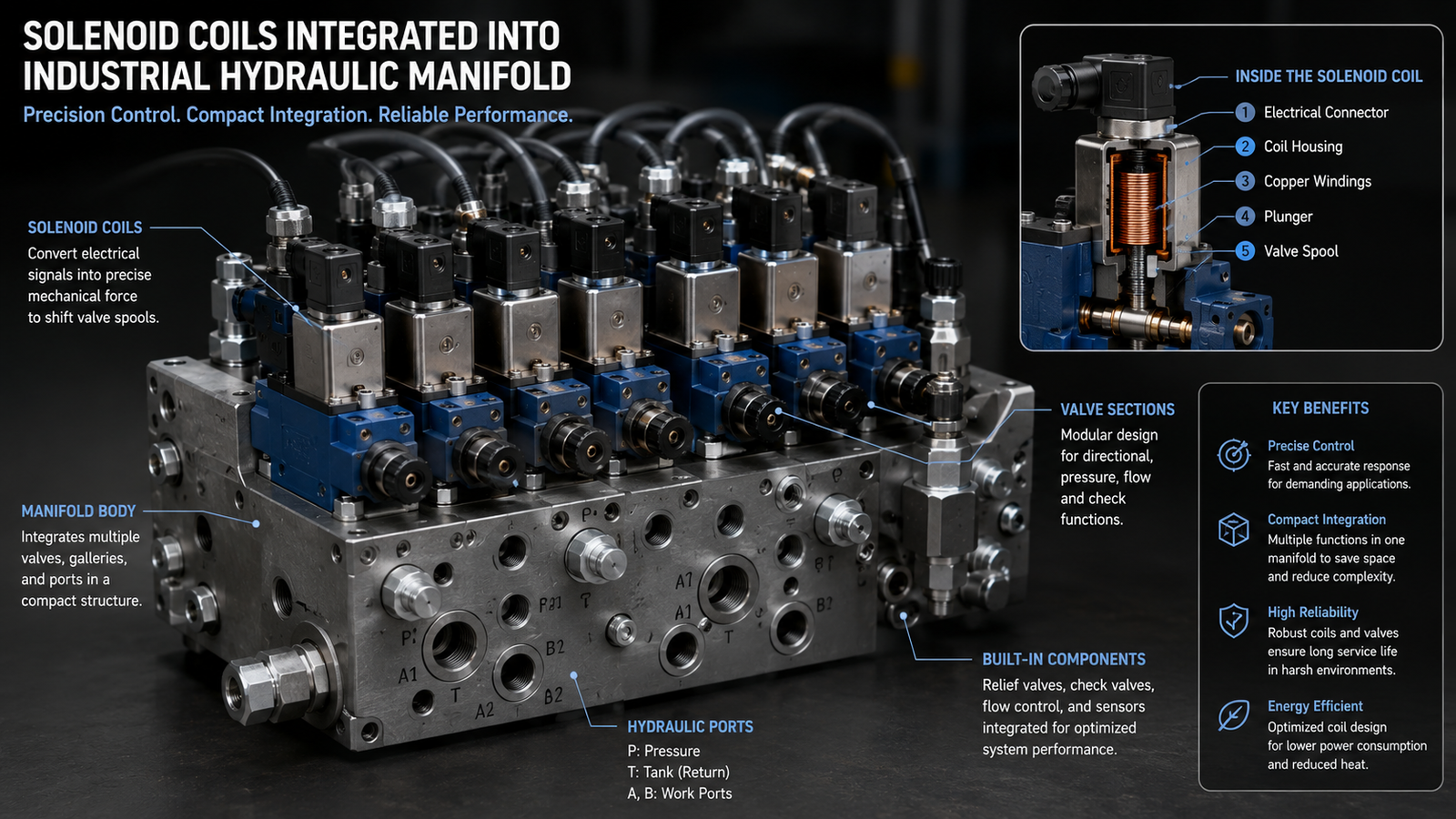
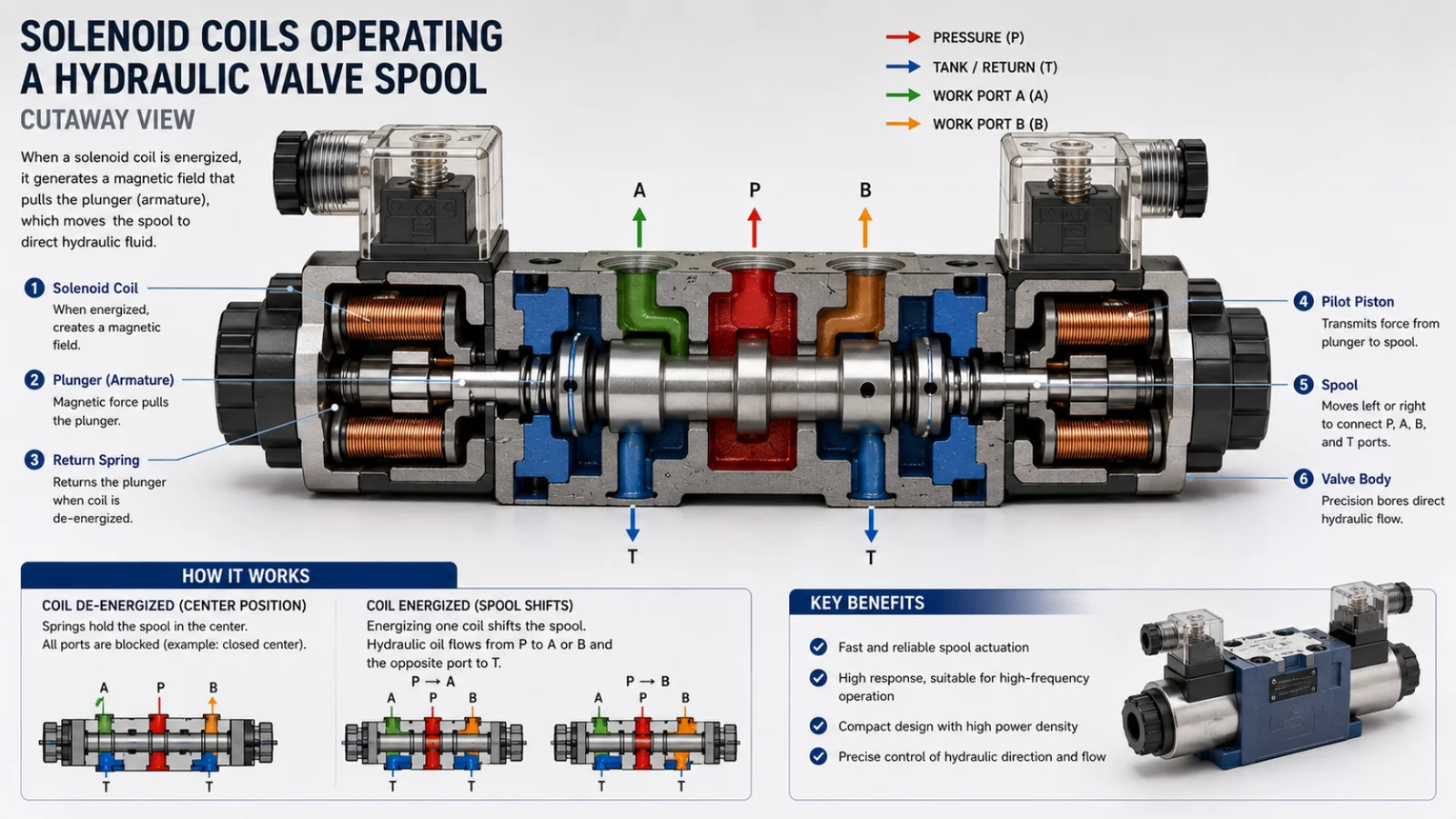
A solenoid coil in a hydraulic valve generates a controlled magnetic field when an electric current passes through its windings.3 This magnetic field exerts force on a ferromagnetic plunger (armature) connected to the valve's spool. This force causes the spool to move, which in turn opens, closes, or adjusts the fluid paths within the valve body.
Dive Deeper: The Engine Behind the Actuation
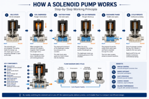
At its core, a solenoid coil operates on the principle of electromagnetism. When electricity flows through the tightly wound copper wire, it creates a linear magnetic field concentrated in the center of the coil. Inside this core sits a movable plunger, typically made of a soft iron alloy. The magnetic field pulls this plunger inward, overcoming the force of a return spring.4
This simple action is the foundation of all solenoid valve control. The coil is the actuator. Without it, the valve is merely a static block of metal with machined passages. Key components include:
- Winding: Composed of high-purity copper wire, its length and gauge determine the coil's electrical resistance and the strength of the magnetic field generated5.
- Bobbin: A plastic or composite frame that the wire is wound around, providing structural integrity and electrical insulation.
- Housing/Encapsulation: A protective shell, often made from engineered thermoplastic, that seals the winding from moisture, dust, and physical damage.
Over my 20 years in manufacturing, I have seen countless projects where upgrading the solenoid coils, not the valve body itself, solved major performance issues related to speed, repeatability, and overheating. The coil isn't just a part of the valve; it's the part that makes the valve work.
How Do Solenoid Coils Work in Switching and Proportional Valves?
You know you need a solenoid-operated valve, but the common industry terms "switching" and "proportional" can be a source of confusion. Choosing the wrong type can result in a system that is either too simplistic for the task or unnecessarily complex and expensive. Understanding how solenoid coils function differently in each valve type is the key to making the right decision for your application.
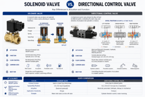
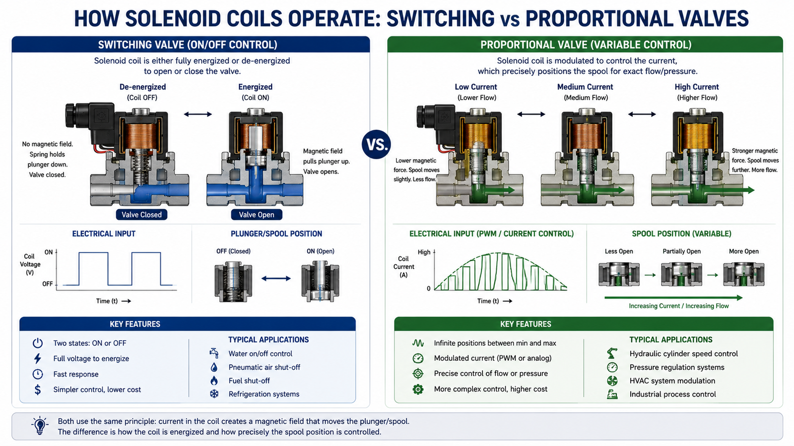
In a switching valve, the solenoid coil operates in a simple ON/OFF digital state, creating a maximum-strength magnetic field to fully shift the valve spool from one position to another. In a proportional valves, the coil receives a variable analog current, creating a magnetic force that is proportional to the input signal and allowing for precise, continuous positioning of the spool.
Dive Deeper: Digital Simplicity vs. Analog Precision
The operational difference between these two coil types is fundamental and directly impacts your system's capabilities. Let's break down each one.
Switching Valves: The Digital Approach (On/Off)
Switching valve coils operate in a binary fashion. When full voltage is applied, the coil generates a powerful magnetic field that slams the valve spool to its fully shifted position. When the power is cut, a spring returns the spool to its default state.
- Function: Their purpose is straightforward directional control—for example, starting or stopping fluid flow, or extending and retracting a hydraulic cylinder.
- Control: The control logic is simple: power on, valve opens; power off, valve closes.
- Advantages: This design offers very fast response times, simple control electronics, and a lower overall cost.
- Use Cases: Ideal for applications like safety shut-offs, basic automation sequences, and diverter circuits where intermediate positions are not needed.
Proportional Valves: The Analog Approach (Precision Control)
Proportional valve coils are engineered for finesse. Instead of a simple on/off signal, they receive a variable current, often managed by a Pulse Width Modulation (PWM) signal. The strength of the magnetic force generated by the coil is directly proportional to the amount of current supplied.6
- Function: By precisely varying the current, you can position the valve spool at any point between fully open and fully closed. This allows for meticulous control over flow rate, pressure, and speed.
- Control: Requires more sophisticated driver electronics that can supply a clean, variable current.
- Advantages: This enables smooth operation, eliminates hydraulic shock (water hammer)7, and facilitates highly accurate, closed-loop control systems.
- Use Cases: Essential for advanced applications like mobile hydraulic equipment (cranes, excavators), industrial automation requiring variable speed, and pressure-regulating systems.
| Feature | Switching Valve Coil | Proportional Valve Coil |
|---|---|---|
| Control Signal | On / Off (Digital) | Variable Current / PWM (Analog) |
| Spool Position | Two discrete positions (fully open/closed) | Continuous, variable positions |
| Function | Directional control, start/stop | Precise flow, pressure, or position control |
| System Complexity | Low | High (requires driver electronics) |
| Typical Use | Simple automation, safety circuits | Closed-loop control, mobile hydraulics |
Where Are Solenoid Coils Commonly Used?
The term "solenoid coil" might sound like a specialized and niche component. This perception can make it difficult to appreciate just how widespread and critical their applications are across major industries that power our modern world. In reality, these essential components are the invisible workhorses behind countless machines we rely on every single day.
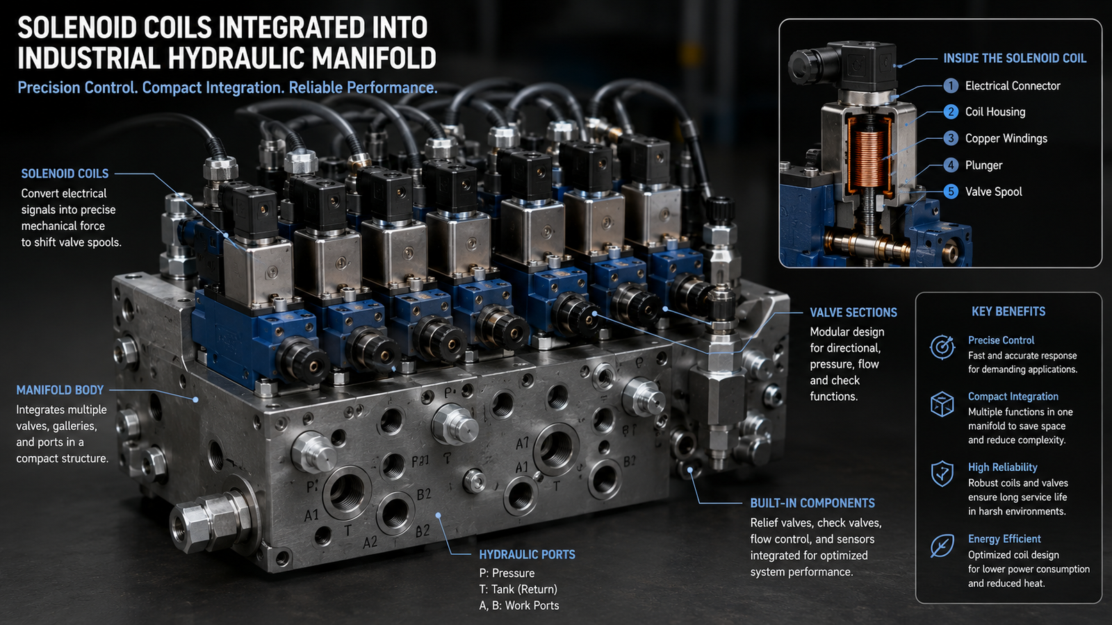
Solenoid coils are ubiquitous in any system requiring automated fluid power control. Key applications include industrial machinery for factory automation, mobile hydraulics in construction and agricultural equipment, automotive systems for transmission and engine control8, and pneumatic systems for sorting and assembly lines.
Dive Deeper: The Unseen Power in Major Industries
The influence of solenoid coils extends across nearly every sector that uses hydraulic or pneumatic power. Their ability to translate a low-power electrical signal into powerful mechanical work makes them indispensable.
- Industrial Machinery: In manufacturing plants, solenoid coils drive the valves that control everything from injection molding machines and metal stamping presses to robotic arms and automated assembly lines. Their speed and repeatability are essential for high-volume production.
- Mobile Hydraulics: This is where proportional solenoid coils truly shine. In an excavator, the operator’s joystick sends variable signals to proportional valve coils. This allows for the incredibly smooth and precise movements of the boom, arm, and bucket that are required for complex tasks. They are also found in tractors, cranes, and forestry equipment.
- Directional Control Valves: This is arguably the most common application. Whether it's a simple switching valve diverting fluid to extend a cylinder or a complex proportional valve manifold steering a mobile machine, the coil is the component that makes the directional control happen.
- Closed-Loop Hydraulic Control: In high-precision systems, a sensor (e.g., a pressure transducer or position sensor) provides real-time feedback to a controller. The controller then constantly adjusts the current to a proportional solenoid coil to maintain a precise setpoint—be it pressure, flow, or position. This is critical for applications like flight simulators and materials testing machines.
- Hydraulic Pumps: Many modern variable displacement pumps use solenoid coils for load-sensing or pressure-compensating controls. The coil adjusts the pump's swashplate angle, changing its output to match system demand perfectly. This drastically improves energy efficiency by ensuring the pump only produces the flow and pressure that is needed at any given moment.
What Features Make a High-Quality Solenoid Coil?
On the surface, most solenoid coils look similar—a spool of copper wire protected by a plastic or metal case. This makes it tempting to choose a supplier based on price alone, but that is a decision that often leads to premature failure, unexpected system downtime, and expensive warranty claims. A truly high-quality solenoid coil is defined by its superior materials, intelligent design, and precision manufacturing, all of which combine to ensure long-term reliability.
A high-quality solenoid coil is characterized by its use of high-purity copper wire for maximum efficiency, superior thermal-class insulation to resist heat, and a robust housing with a high IP rating for environmental protection. Critically, it must also feature precision winding techniques to ensure consistent magnetic force from one coil to the next.
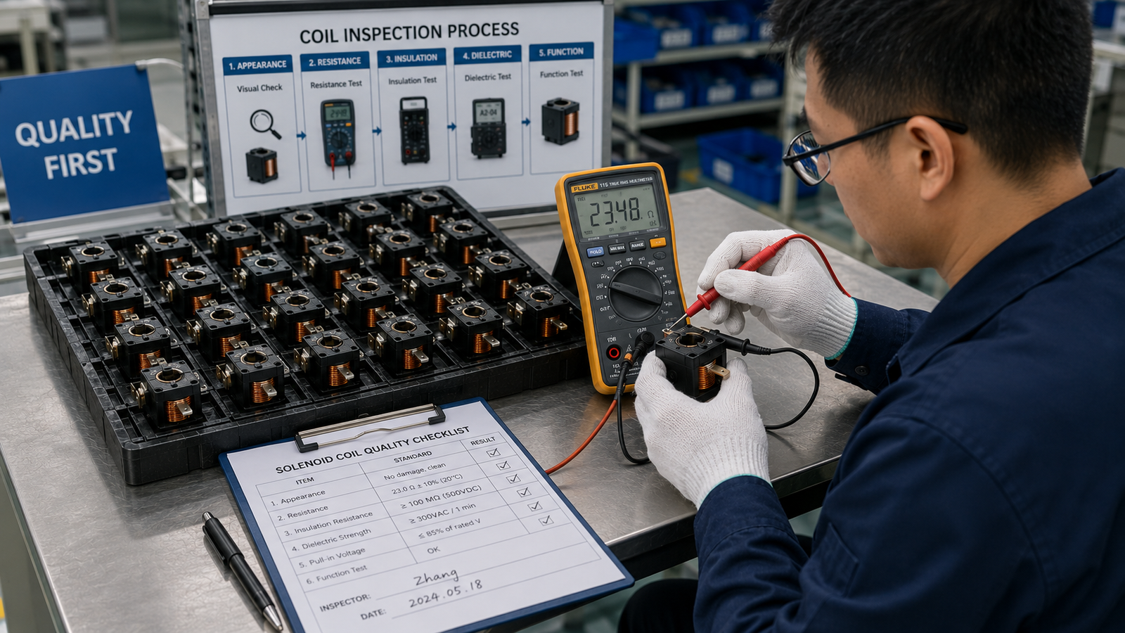
Dive Deeper: Engineering for Reliability and Performance
As an OEM/ODM manufacturer for leading European brands, we know that quality is not an accident; it is engineered. Here are the features that separate a premium coil from a standard one.
Material and Construction Excellence
- Winding Wire: The process starts with high-purity, oxygen-free copper wire. This minimizes electrical resistance, reducing heat generation (I²R losses) and improving overall efficiency. The winding process itself must be automated and precise to guarantee that every coil has the exact same number of turns, ensuring a consistent magnetic field and predictable force output.9
- Bobbin and Insulation: The coil's ability to withstand heat is determined by its thermal class rating. This is a function of the bobbin material (e.g., high-temperature PA66 nylon, PBT) and the enamel insulation on the copper wire. A higher thermal class (e.g., Class H, 180°C) allows the coil to operate in hotter environments or under continuous duty without degradation.10
- Housing and Encapsulation: The outer shell does more than just provide a clean look. It is a critical barrier against environmental hazards. A high-quality coil is fully encapsulated in a void-free thermoplastic, which prevents moisture ingress and protects the delicate windings from shock and vibration. This is where the IP rating (e.g., IP65, IP67) becomes a key indicator of durability.
Design for Durability and Serviceability
- Shock and Vibration Resistance: For mobile equipment, coils must withstand constant shaking and impact. Robust designs secure the internal winding within the encapsulation and utilize durable, locking connector systems like Deutsch or AMP to prevent electrical interruptions.
- Voltage and Power Versatility: A reliable manufacturer offers a wide range of standard voltage options (e.g., 12V DC, 24V DC) to meet global application needs. They also have the engineering capability to design custom voltages and power ratings for specific OEM requirements.
- Ease of Installation and Maintenance: Smart design features make a big difference in the field. This includes rotatable connectors that can be oriented for easy wiring access, standardized mounting interfaces (DIN connectors), and simple locking nuts that allow for quick replacement without breaking hydraulic lines.
- Integrated Protection Circuits: When a DC coil is de-energized, the collapsing magnetic field can induce a large voltage spike (inductive kickback) that can damage sensitive control electronics like PLCs or microcontrollers11. Premium coils can be manufactured with an integrated flyback diode to safely dissipate this energy, protecting the rest of your system.
How Do You Choose the Right Solenoid Coil?
You have identified the need for a coil and are ready to begin the procurement process, but the specification sheet is filled with technical jargon. Making the wrong selection can directly compromise the performance and safety of your entire product, potentially leading to customer dissatisfaction and long-term damage to your brand's reputation. Following a systematic approach ensures you select the perfect solenoid coil that meets your performance, reliability, and cost targets.
To choose the right solenoid coil, you must first methodically match its specifications to your application's demands. The most critical factors to define are the required operating voltage, the type of valve it will control (switching or proportional), its duty cycle, the harshness of the operating environment (which dictates the IP rating), and the necessary connector type for seamless integration.

Dive Deeper: A Procurement Manager's Checklist
As a procurement or brand manager, your goal is to source a component that delivers stable performance and minimizes risk. This checklist will guide you from technical requirements to a sound purchasing decision.
-
Operating Voltage and Power: The first step is to match the coil's voltage rating (e.g., 12V DC, 24V DC, 110V AC) to your machine's available power supply. A voltage mismatch is a common cause of failure; too low, and the valve won't actuate reliably; too high, and the coil will quickly overheat and burn out. Also, consider the power consumption (in watts), as this affects heat generation and the load on your power supply.
-
Valve Type Compatibility: Is this for a simple ON/OFF switching valve or a precision proportional valve? As we've discussed, the coil designs are fundamentally different. A switching coil cannot provide proportional control, and a proportional coil will not function correctly with a simple on/off signal. Confirm this with your engineering team.
-
Duty Cycle (Continuous vs. Intermittent): Will the coil be energized for long periods? A 100% or "continuous duty" rated coil is designed to stay on indefinitely without overheating. An "intermittent duty" coil is designed for brief activation periods followed by a cool-down time. Using an intermittent coil in a continuous application is a guarantee of premature failure.
-
Operating Environment (Temperature and Ingress Protection): You must specify a coil that can survive its working environment. Consider the ambient temperature range and whether the coil will be exposed to water, dust, oil, or chemicals. This will determine the required thermal class and IP (Ingress Protection) rating. A coil on an excavator arm exposed to rain needs at least an IP67 rating.
-
Response Speed: For high-speed automation, the time it takes for the valve to actuate is critical. High-performance solenoid coils are designed with materials and geometries that allow the magnetic field to build and collapse more quickly, enabling faster cycle times.
-
Connectors and Installation: How will the coil connect to your machine's wiring harness? Common options include DIN 43650, Deutsch, AMP Junior Timer, or simple flying leads. Selecting the correct connector upfront saves significant time and cost during final assembly. Also, confirm the coil's physical dimensions and mounting style will fit your valve.
When in doubt, partner with an experienced manufacturer. At SolenElec, our engineering team works directly with our clients' procurement and technical teams to analyze these requirements and specify or custom-design the ideal coil for their application.
Frequently Asked Questions
What happens if you use the wrong voltage on a solenoid coil?
Using a voltage lower than specified will generate a weak magnetic field, which may be insufficient to actuate the valve, especially under load. Conversely, applying a higher voltage will cause the coil to draw excessive current, leading to rapid overheating, insulation breakdown, and burnout.
What is a coil's 'duty cycle'?
Duty cycle refers to the percentage of time a solenoid coil can be safely energized within a given period without damage from overheating. A coil rated for "100% duty cycle" or "continuous duty" can be left on indefinitely. An intermittent-duty coil must be cycled on and off to allow it to cool.
Can I replace a switching valve coil with a proportional valve coil?
No, they are not interchangeable. While they might look similar, their internal winding characteristics and electrical requirements are fundamentally different. A proportional coil needs a specialized PWM driver to function, and a switching coil is designed for a simple full-voltage ON/OFF signal.
What does the IP rating on a solenoid coil mean?
The IP (Ingress Protection) rating is a standardized system that classifies the degree of protection a coil's enclosure provides against the intrusion of solids (like dust) and liquids (like water). For example, an IP65 rating signifies the coil is dust-tight and protected against water jets from any direction.12
Conclusion
Ultimately, the solenoid coil is far more than a simple component; it is the active heart of any modern switching or proportional valve. The quality of its design and manufacturing directly dictates the precision, speed, and long-term reliability of your entire hydraulic or pneumatic system. From industrial automation to heavy-duty mobile machinery, the performance of the final product rests on this critical electromechanical actuator. Therefore, choosing the right solenoid coils by carefully matching them to the valve type, operating voltage, and working environment is a decision as critical as selecting the valve itself.
For over 20 years, SolenElec has specialized in the OEM/ODM manufacturing of high-performance, custom solenoid coils for leading global brands. If you are looking for a reliable partner to help guarantee your product's performance and uphold your brand's reputation for quality, contact our engineering team to discuss your next project.
Need Help Selecting the Right Solenoid Coil?
Whether you need switching coils, proportional valve coils, or a custom OEM solution, choosing the correct coil design is critical for valve performance, response speed, and long-term reliability.
👉 Contact us to discuss your project with our engineering team.
"How Solenoid Valves Work: The Complete Guide", https://imba.missouri.edu/how-solenoid-valves-work-3857534400.html. Engineering references on solenoid valves describe the coil as an electromagnetic actuator that converts an electrical input into magnetic force on an armature or plunger, thereby producing valve motion. Evidence role: mechanism; source type: education. Supports: The source should explain that current through a solenoid coil creates a magnetic field that moves an armature or plunger to actuate a valve.. ↩
"Understanding the Concepts of Proportional Valves in Ten ...", https://www.academia.edu/33032859/Understanding_the_Concepts_of_Proportional_Valves_in_Ten_Minutes_by_JOJI_Parambath_Author_Industrial_Hydraulic_Systems_Theory_and_Practice. Technical descriptions of solenoid valves distinguish on/off valves, which shift between discrete states, from proportional valves, which vary spool position and hydraulic output in response to a controlled electrical input. Evidence role: definition; source type: education. Supports: The source should define the functional difference between on/off solenoid valves and proportional solenoid valves.. ↩
"Solenoid", https://en.wikipedia.org/wiki/Solenoid. General electromagnetic references explain that an electric current passing through a solenoid winding produces a magnetic field concentrated along the coil axis. Evidence role: mechanism; source type: encyclopedia. Supports: The source should support the electromagnetic principle that current in a solenoid winding produces a magnetic field.. Scope note: This supports the physical principle of field generation rather than the performance of any specific hydraulic valve design. ↩
"How Solenoid Valves Work: The Complete Guide", https://imba.missouri.edu/how-solenoid-valves-work-3857534400.html. Engineering explanations of solenoid actuators state that energizing the coil magnetizes the magnetic circuit and attracts the armature or plunger, commonly against a spring that restores the default position when power is removed. Evidence role: mechanism; source type: education. Supports: The source should describe how energized solenoids move a ferromagnetic plunger or armature against spring force.. ↩
"Solenoid", https://en.wikipedia.org/wiki/Solenoid. Electrical engineering references show that wire length and cross-sectional area determine conductor resistance, while solenoid field strength depends on current, turns, and geometry. Evidence role: mechanism; source type: education. Supports: The source should explain that conductor dimensions affect resistance and that solenoid geometry, turns, and current affect magnetic field strength.. Scope note: The source may support the underlying design relationships rather than proving the exact effect for a particular commercial coil. ↩
"Chapter 4: ElectroMagnetic Actuator Basics", http://commons.princeton.edu/motorcycledesign/wp-content/uploads/sites/70/2018/07/solenoid.pdf. Studies of proportional solenoid actuators describe current-controlled magnetic force as the basis for proportional valve control, while noting that the force-current relationship can vary with air gap, stroke, and magnetic saturation. Evidence role: mechanism; source type: paper. Supports: The source should support that proportional solenoids are designed so output force or spool position can be controlled by input current.. Scope note: This supports current-dependent control behavior but may not justify a perfectly linear or universally 'directly proportional' relationship. ↩
"(PDF) WATER HAMMER: PRACTICAL SOLUTIONS", https://www.academia.edu/6868339/WATER_HAMMER_PRACTICAL_SOLUTIONS. Research on hydraulic transients indicates that controlled valve motion and gradual flow changes can reduce pressure surges associated with water hammer or hydraulic shock. Evidence role: general_support; source type: paper. Supports: The source should support that controlled valve actuation, ramping, or proportional flow control can reduce pressure transients associated with hydraulic shock or water hammer.. Scope note: This supports mitigation of hydraulic shock; it does not prove that proportional valves eliminate it under all system conditions. ↩
"Electronic Transmission Control", https://cecas.clemson.edu/cvel/auto/systems/transmission_control.html. Automotive engineering references identify solenoid valves as common actuators in automatic transmission hydraulic control and in selected engine control functions. Evidence role: case_reference; source type: education. Supports: The source should document that solenoid valves or solenoid actuators are used in automotive transmissions and engine management systems.. Scope note: This supports representative automotive uses, not the prevalence or design details of every vehicle platform. ↩
"History of electromagnetic theory", https://en.wikipedia.org/wiki/History_of_electromagnetic_theory. Electromagnetic design references state that solenoid magnetic field strength depends in part on the number of coil turns and current, so variation in winding turns can affect repeatability of magnetic output. Evidence role: mechanism; source type: education. Supports: The source should support that solenoid magnetic field strength depends on the number of turns and current, making winding consistency relevant to repeatable output.. Scope note: This supports the physical basis for winding consistency, not the necessity of automation in every manufacturing context. ↩
"Insulation system", https://en.wikipedia.org/wiki/Insulation_system. Electrical insulation standards define thermal classes for insulating systems, including Class H with a 180°C temperature rating, which is used to specify allowable thermal endurance. Evidence role: definition; source type: institution. Supports: The source should define insulation thermal classes and confirm that Class H corresponds to a 180°C temperature rating.. Scope note: The rating indicates insulation temperature capability; actual continuous-duty suitability also depends on coil design, heat dissipation, ambient temperature, and duty cycle. ↩
"Understanding the behavior of 1200 V SiC MOSFET under ...", https://research.ece.ncsu.edu/wp-content/uploads/sites/10/2019/07/etd33.pdf. Electronics references on inductive loads explain that interrupting current through a solenoid coil can produce a voltage transient, and that flyback diodes or related suppression devices are used to protect control circuits. Evidence role: mechanism; source type: education. Supports: The source should explain that interrupting current through an inductive coil can create a voltage transient and that flyback protection is used to protect switching electronics.. ↩
"IP code", https://en.wikipedia.org/wiki/IP_code. The IEC ingress-protection classification defines IP65 as dust-tight protection against solid particles and protection against water jets directed at the enclosure. Evidence role: definition; source type: institution. Supports: The source should define the two digits of IP65 as complete protection against dust ingress and protection against water jets.. ↩