How to Choose the Right DIN Connector Coil for Your Solenoid Valve?
DIN connector coils are widely used in industrial automation and fluid control systems. Understanding different solenoid coil types and applications can help engineers make better sourcing decisions.Choosing the wrong coil invites field failures and warranty claims that damage your brand. A better approach matches the component to the application, managing risk before it becomes a cost.
To choose the right DIN connector coil, shift your focus from unit price to total cost of ownership. The best choice is a risk management decision that matches the coil's material, IP rating, and thermal properties to your specific application to minimize long-term failure costs.
I’ve spent over 20 years working with procurement managers at major appliance brands, and I see the same challenge repeatedly. You are not just buying a part; you are making a strategic decision to protect your brand's reputation. The key isn't finding a single "best" coil, but finding the most reliable coil for a specific environment. Let's break down how to make that decision, based on the questions we hear every day from buyers like you.
What Are DIN Connector Coils and Which Standard (Form A, B, or C) Do You Need?
You're evaluating suppliers, but a simple mismatch in connector size can halt your production line. Connector selection should be evaluated together with environmental protection requirements, vibration resistance, and electrical specifications. Learn more about solenoid coil connectors and performance reliability.This confusion over DIN forms is a common but easily avoidable procurement headache.
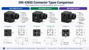
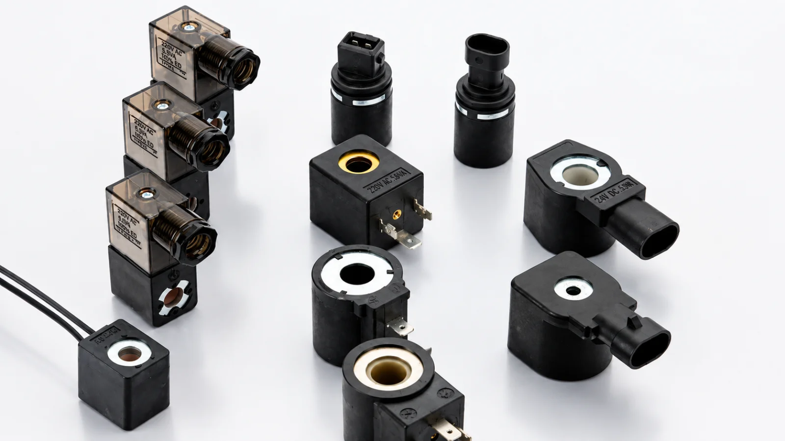
DIN 43650 standards define the connector's physical size and pin layout.1 Form A is the largest, for high-power industrial use. Form B is medium-sized, common in mobile hydraulics. Form C is the smallest, often used in compact pneumatic and appliance applications.
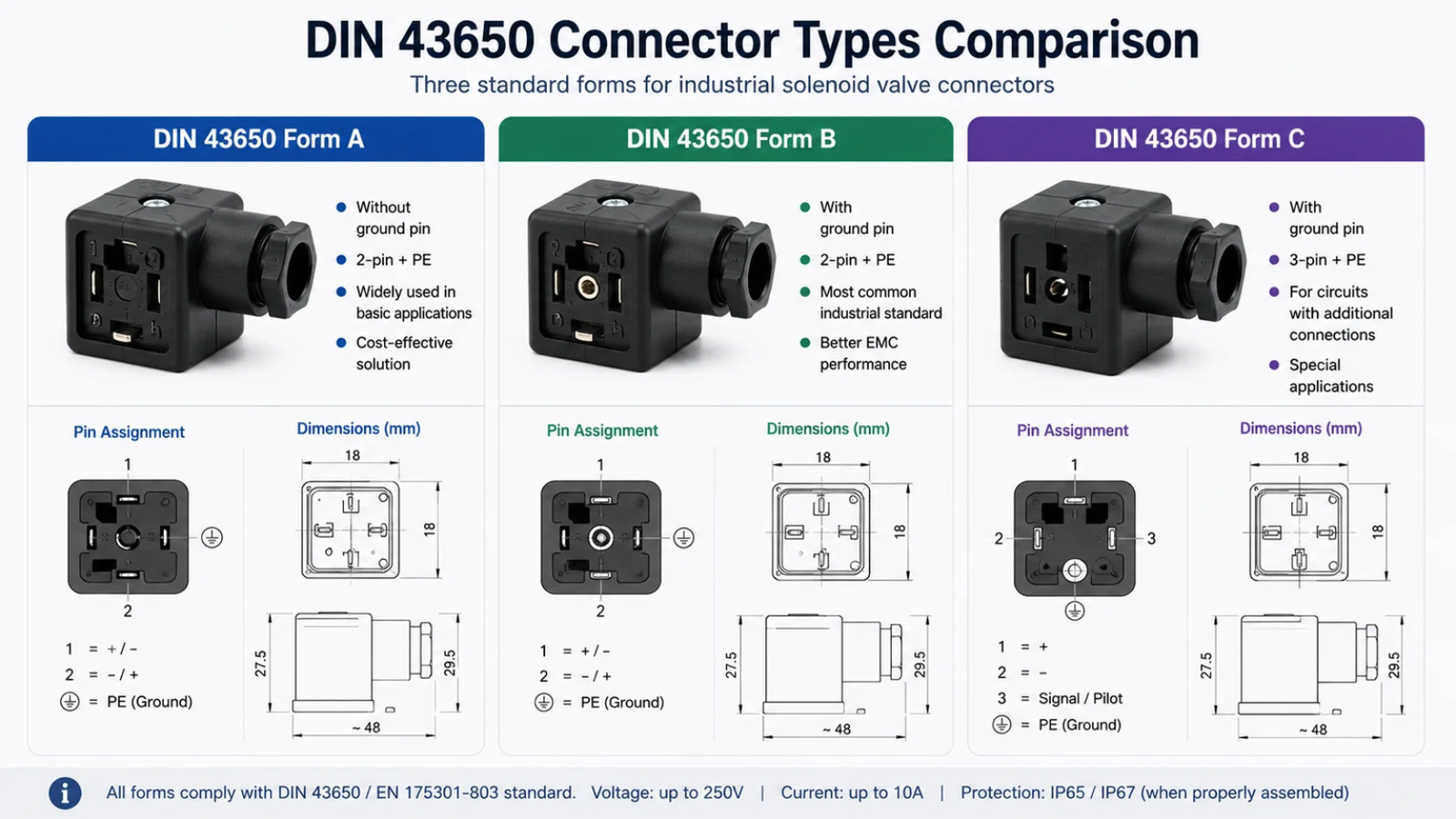
Getting the DIN form right is the first and most fundamental step. While it seems basic, we've received calls from new purchasing managers who inherited a project and approved a coil based on voltage alone, only to find it physically won't connect to their valve. This is about more than just pin spacing; it dictates the power handling and overall size of the assembly.2
Matching Form to Application
Think of this as the initial handshake between your valve and the coil. If the handshake fails, nothing else matters. The different forms were created for different physical and electrical needs.
| Feature | Form A | Form B | Form C |
|---|---|---|---|
| Pin Spacing | 18 mm | 10 mm or 11 mm | 8 mm or 9.4 mm3 |
| Gasket Shape | U-Shaped | Flat rectangular | Flat rectangular |
| Typical Use | High-power industrial | General-purpose hydraulics | Compact pneumatics4 |
| Common Current | Up to 10A | Up to 10A | Up to 6A |
For most home appliance applications I see, space is at a premium. This often pushes designers toward Form C. However, if the valve requires higher current or is in a more demanding environment, the larger, more robust Form A might be necessary. Your decision must balance the electrical requirements with the physical constraints of your product design.
How Do You Correctly Wire and Test a DIN 43650 Solenoid Coil Connector?
Improper wiring is a frequent point of failure found during production line testing. This simple error can cause shorts, prevent operation, and lead to unnecessary component scrappage and delays.
For a standard 3-pin connector, connect Pin 1 to the live/positive wire and Pin 2 to the neutral/negative wire. The central pin, marked with a ground symbol, must be connected to earth for safety. Before applying power, test the resistance across pins 1 and 2 with a multimeter.
From our experience in post-project analysis for appliance brands, a surprising number of failures trace back to incorrect assembly on the factory floor. Providing clear instructions and a simple test procedure is critical for quality control. This isn't just about making the coil work; it's about ensuring safety and consistency.
A Simple Pre-Power Test
Before a coil is ever energized in a final product, a quick two-step check with a multimeter can prevent a dead-on-arrival failure. Always perform these tests with the power disconnected.
-
Resistance Check: Set your multimeter to the Ohms (Ω) setting. Place one probe on Pin 1 and the other on Pin 2. You should get a resistance reading, not zero and not infinite. An infinite reading (OL) means the coil winding is broken. A reading of zero means there is a short circuit inside the coil. The exact resistance value will vary based on the coil's design, but a concrete reading confirms the circuit is complete.
-
Ground Fault Check: Keep one probe on the ground pin. Touch the other probe to Pin 1, then to Pin 2. In both cases, the multimeter should show an infinite reading (OL). Any resistance reading here indicates a short to ground, a dangerous condition that could energize the valve's body.
This simple process takes seconds but verifies the coil is internally sound and safe to install. It's a non-negotiable step for any high-volume production line.
How Do Overmolded DIN Coils Achieve Superior IP65 and IP67 Moisture Protection?
Moisture kills electronics, and a standard coil will quickly fail in a dishwasher or coffee machine. This risk of moisture ingress leads to costly field failures and erodes customer trust.
Overmolding completely seals the copper winding and internal electronics in a solid, seamless block of thermoplastic. This process eliminates air gaps and weak points, creating a monolithic barrier that is impenetrable to dust and water, thereby achieving high IP ratings like IP65 and IP67.5
When a procurement manager asks us about reliability in wet environments, the conversation always turns to encapsulation. It's not enough to just put a plastic case around the coil; the manufacturing process itself is key to long-term protection. Overmolding is a process where we place the finished coil winding into an injection mold and then inject molten thermoplastic (like PA66 or PBT) under high pressure. This ensures the plastic flows into every tiny crevice, bonding directly to the coil and terminals.
Material Choice and Protection Level
The choice of overmolding material is just as critical as the process itself. For a coffee machine, where the coil is exposed to high heat and steam, a material with a high glass transition temperature like PBT is often superior. For other applications, a durable and cost-effective material like PA66 with glass fiber might be sufficient. This is a crucial discussion to have with your supplier.
Understanding IP ratings in this context is essential:
- IP65: The coil is protected against low-pressure water jets from any direction. This is the minimum for an appliance like a dishwasher where splashing is expected.
- IP67: The coil is protected against temporary immersion in water up to 1 meter deep. This provides a higher safety margin for devices where flooding or more significant water contact is possible.
Choosing a higher-rated, properly overmolded coil is an investment in preventing water-related warranty claims.
Why Should You Choose a DIN Connector with Built-In LED Indicators and Surge Suppression?
A machine is down, and troubleshooting is taking hours. Is the valve getting power, or has the coil failed? This diagnostic guesswork costs time and money for your service teams.
An LED provides immediate visual confirmation that the coil is receiving power, dramatically speeding up troubleshooting. Built-in surge suppression, typically a varistor, absorbs voltage spikes when the coil de-energizes6, protecting both the coil and sensitive control circuits from damage.

We often discuss Total Cost of Ownership (TCO) with brand managers, and this is a perfect example. The small added cost of a connector with these features pays for itself the first time a technician is dispatched for a service call. Instead of needing a multimeter and time to diagnose a power issue, the technician can see the problem instantly. If the LED is on but the valve isn't shifting, the problem is likely mechanical. If the LED is off, the problem is in the control signal or wiring.
Protecting Your System from Itself
Surge suppression is an equally important, though less visible, feature. When a DC solenoid coil is switched off, the collapsing magnetic field induces a large reverse-voltage spike (back EMF). This spike can be several times the nominal operating voltage.7
| Feature | Standard Connector | Connector with LED & Suppression |
|---|---|---|
| Troubleshooting | Requires multimeter to check for voltage | Instant visual check via LED |
| Circuit Protection | None. Voltage spikes can damage controls. | Built-in varistor absorbs spikes. |
| Service Cost | Higher diagnostic time | Lower diagnostic time |
| System Reliability | Lower, vulnerable to power surges | Higher, protected from back EMF |
In modern appliances that rely on microcontroller-based boards, these voltage spikes can damage the output drivers or even the processor itself. A simple varistor inside the DIN connector shorts this spike, protecting the entire control system. It's a tiny, inexpensive component that acts as crucial insurance against electronic failure, improving the longevity of your entire product.
How Do You Source High-Volume DIN Connector Coils with Custom Voltages and Duty Cycles?
You have a unique product design, but off-the-shelf coils don't meet your voltage or performance needs. Sourcing a custom component for high-volume production feels complex and full of risk.
Selecting the wrong voltage or power rating can lead to overheating and premature failure. Follow this detailed solenoid coil selection guide for industrial valves.
The key is to partner with an experienced OEM/ODM manufacturer with in-house engineering. They can modify winding specifications for custom voltages (e.g., 24VDC, 120VAC) and design the coil's thermal properties specifically for its intended duty cycle, ensuring it doesn't overheat in continuous operation.
A common question we hear from procurement managers is, "Can you make a 12VDC coil that can stay on all day?" This question is about more than just voltage; it's about duty cycle and thermal management. A coil designed for intermittent use will quickly overheat and fail if left on continuously (100% duty cycle). A true 100% duty cycle coil requires careful design, including the right wire gauge, number of turns, and bobbin material (like PBT or LCP) to effectively dissipate heat. This prevents the insulation from breaking down, which is the primary cause of thermal failure.
Asking the Right Questions
Instead of focusing only on price, you should ask questions that reveal a supplier's true capabilities for long-term reliability. Our most successful partners—brands with low warranty claims—ask the following:
- "What is the coil's insulation class and maximum operating temperature?" This tells you how much heat the coil can handle before the enamel on the copper wire degrades. For a hot application, you need a Class F (155°C) or Class H (180°C)8 coil.
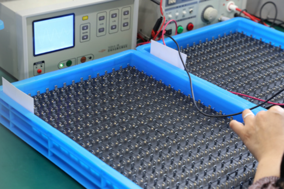
- "What is your process for ensuring consistency in winding and molding across a 100,000-unit batch?" A reliable supplier will talk about automated winding machines and using MES systems for process control and traceability, ensuring the first coil performs identically to the last.
As an OEM/ODM manufacturer for over 20 years, we’ve built our systems around these questions. Our ISO 9001 and IATF 16949 certified production lines are designed for this consistency. That's how you reduce procurement risk.
Conclusion
Choosing the right DIN coil is about managing risk. Match the coil's material, protection, and thermal design to its real-world application to ensure reliability and protect your brand reputation.
Need Help Selecting the Right DIN Connector Coil?
Choosing the right DIN connector coil involves more than matching dimensions. Electrical performance, environmental protection, and long-term reliability should all be considered.
Explore our Solenoid Coil Product Line or Contact Our Engineering Team for application-specific recommendations.
"DIN 43650 Form A Connectors - Products for Automation", https://www.productsforautomation.com/din-43650-form-a-valve-connectors-a/588.htm. The EN 175301‑803 (formerly DIN 43650) standard describes the rectangular connectors used with solenoid valves, including their physical dimensions and pin configurations, supporting the statement that the standard defines size and pin layout; detailed dimensional tables are contained in the standard itself and summarized in secondary references. Evidence role: definition; source type: encyclopedia. Supports: That the connector dimensions and pin arrangements are specified by the DIN 43650/EN 175301-803 standard for solenoid valve connectors.. ↩
"Type 2516 data sheet | Cable plug DIN EN 175301-803", https://docs.rs-online.com/8b12/A700000007049793.pdf. Reference material on EN 175301‑803 notes that Forms A, B, and C differ in physical dimensions and typical current capacity, providing contextual support that connector form influences power handling and overall assembly size; specific current ratings depend on connector design and certification. Evidence role: general_support; source type: encyclopedia. Supports: That different connector forms under EN 175301-803 have distinct sizes and typical permissible current ratings, linking form choice to power handling and assembly size.. ↩
"Solenoid DIN Connectors EN 175301-803 ,Form Factor-C", https://www.hydraulicmegastore.com/product/kd136v54t7/. Summaries of EN 175301‑803 connector variants list Form C styles with pin spacings around 8 mm and approximately 9.4 mm, supporting the dimensional values given; exact measurements can vary by subtype and manufacturer, with authoritative values specified in the standard. Evidence role: definition; source type: encyclopedia. Supports: That Form C connectors are available in variants with approximately 8 mm and 9.4 mm pin spacing.. ↩
"Type 6526 - 3/2-way solenoid valve for pneumatic applications", https://www.burkert-usa.com/en/type/6526. Encyclopedic overviews document EN 175301‑803 connectors as used with solenoid valves in pneumatic and hydraulic systems and identify Form C as the smallest style, which contextually supports its use in compact pneumatics; exact application choices vary by device design and requirements. Evidence role: general_support; source type: encyclopedia. Supports: That EN 175301-803 connectors are widely used with solenoid valves in pneumatic systems and that smaller connector forms are suited to compact devices.. ↩
"IP code - Wikipedia", https://en.wikipedia.org/wiki/IP_code. IEC 60529 defines IP65 as dust‑tight and protected against water jets and IP67 as dust‑tight with temporary immersion protection; electronics encapsulation/potting is documented as a method to enhance resistance to moisture ingress, which together supports the assertion that sealed overmolded coils can meet high IP ratings, noting that compliance must be verified by testing the complete assembly. Evidence role: definition; source type: encyclopedia. Supports: That IP65 and IP67 have defined levels of dust and water protection, and that encapsulation/potting is used to improve moisture resistance in electronics.. ↩
"Varistor - Wikipedia", https://en.wikipedia.org/wiki/Varistor. Varistors are characterized as nonlinear voltage‑dependent resistors used to clamp transient overvoltages, including those generated at turn‑off of inductive loads, supporting the role described for surge suppression; the effectiveness depends on device selection and circuit conditions. Evidence role: mechanism; source type: encyclopedia. Supports: That varistors clamp transient overvoltages from inductive switching events to protect circuits.. ↩
"inductor - Inductive kickback - Electrical Engineering Stack Exchange", https://electronics.stackexchange.com/questions/398922/inductive-kickback. Technical summaries of inductive kickback explain that when current through an inductor is interrupted, the collapsing magnetic field produces a high reverse‑polarity voltage spike that, without suppression, can exceed the supply voltage by multiple times, consistent with the claim; actual peak values depend on inductance, current, and circuit parasitics. Evidence role: mechanism; source type: encyclopedia. Supports: That interrupting current in an inductor generates high reverse-voltage spikes that can exceed the supply voltage absent suppression.. ↩
"Insulation system - Wikipedia", https://en.wikipedia.org/wiki/Insulation_system. IEC 60085 specifies thermal classes for electrical insulation systems, identifying Class F as 155 °C and Class H as 180 °C, directly supporting the stated temperature ratings for coil insulation selection. Evidence role: definition; source type: institution. Supports: That IEC thermal insulation classes specify Class F at 155°C and Class H at 180°C.. ↩