Struggling with unexpected solenoid valve failures? Many engineers choose a solenoid valve connector based only on its size, but this common oversight can lead to system breakdowns, moisture ingress, and costly downtime. The real solution lies in looking beyond the basic DIN form factor and matching the connector to the unique demands of your specific operating environment.
To choose the right solenoid valve connector, you must look beyond standard DIN form factors and evaluate the application’s complete context. This includes matching the electrical specifications (voltage and current) to the coil, selecting an appropriate Ingress Protection (IP) rating for the environment, and deciding if you need diagnostic features like LED indicators or protective circuitry for surge suppression. A holistic evaluation ensures long-term system reliability and reduces maintenance costs.
Choosing the right connector is one of the most cost-effective ways to improve the long-term reliability of your equipment. But with so many options, how do you make the right choice? Let's dive deeper into what defines a connector and the critical factors you need to consider.
What Is a Solenoid Valve Connector?
Many people see it as just a simple plug, but failing to appreciate its role can lead to poor component choices and system vulnerabilities. Are you sure you understand what this small but mighty component actually does?
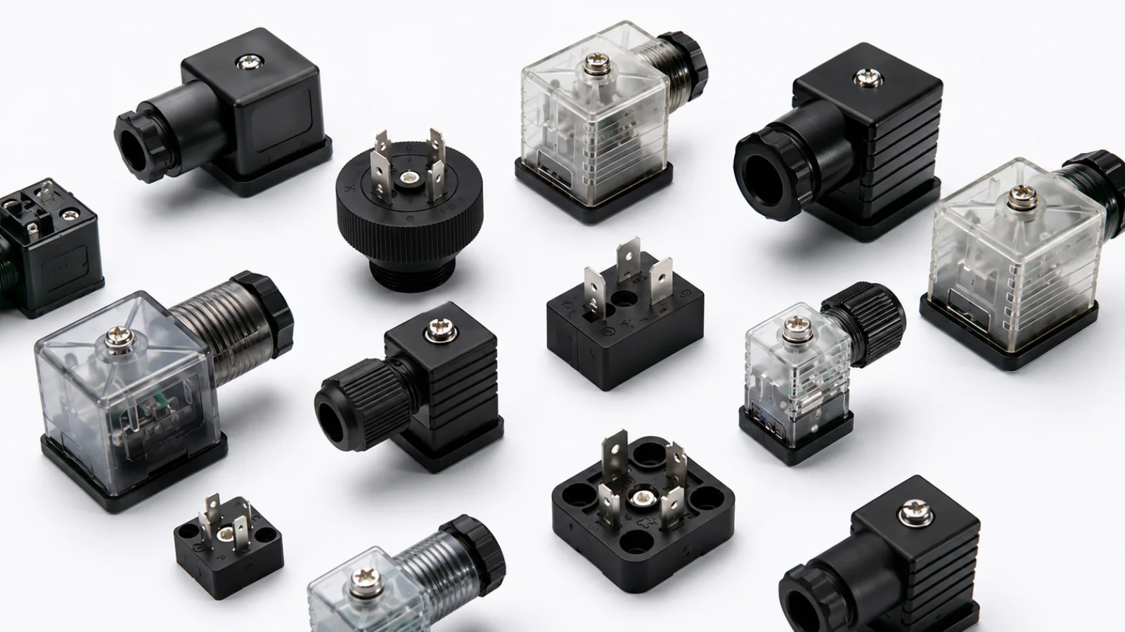
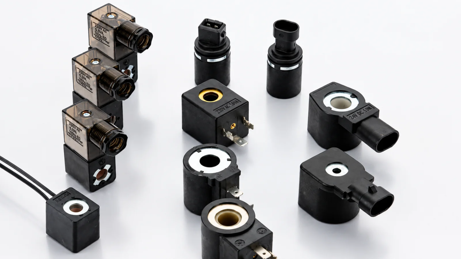
A solenoid valve connector is a specialized housing that creates a secure electrical interface between a power source and a solenoid coil, enabling the valve to actuate. More importantly, it serves as a protective enclosure, shielding the delicate electrical contacts from moisture, dust, vibration, and impact.
Dive Deeper
At its core, a solenoid valve connector is the critical link that delivers power to the solenoid coil, which in turn creates the magnetic field needed to shift a valve1. But its function extends far beyond simple power transmission. A well-designed connector is fundamental to system integrity. Think of it as a gatekeeper for your solenoid coil.
A complete connector assembly typically consists of four main parts:
- The Housing: The outer shell, usually made of a durable polymer like polyamide (PA), protects the internal components.
- The Gasket: A flat or profiled seal that sits between the connector and the coil. This is crucial for achieving the specified Ingress Protection (IP) rating.
- The Contact Insert: This block holds the electrical terminals where the wires are connected.
- The Cable Gland and Screw: A compression fitting that secures the cable and seals it against the environment, preventing contaminants from entering the housing.
In my 20 years of experience as an OEM manufacturer, I've seen countless failures that were traced back not to the coil itself, but to a compromised connection. A connector that fails to protect against moisture will lead to corrosion and short-circuits. One that can't withstand vibration will cause intermittent power loss and erratic valve operation. Choosing a quality solenoid valve connector is just as important as choosing the right coil.
What Are the Common Solenoid Valve Connector Types?
With terms like Form A, B, and C thrown around, it's easy to get confused. Choosing the wrong form factor means the connector simply won't fit, stopping your assembly process dead in its tracks. So, let's clarify what these standards mean.
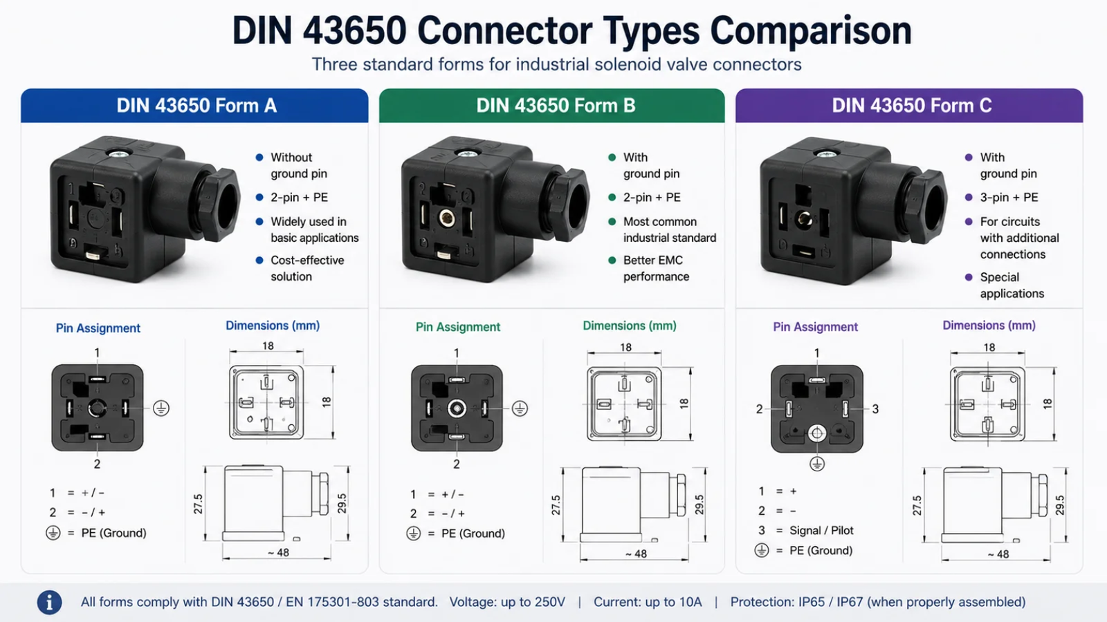
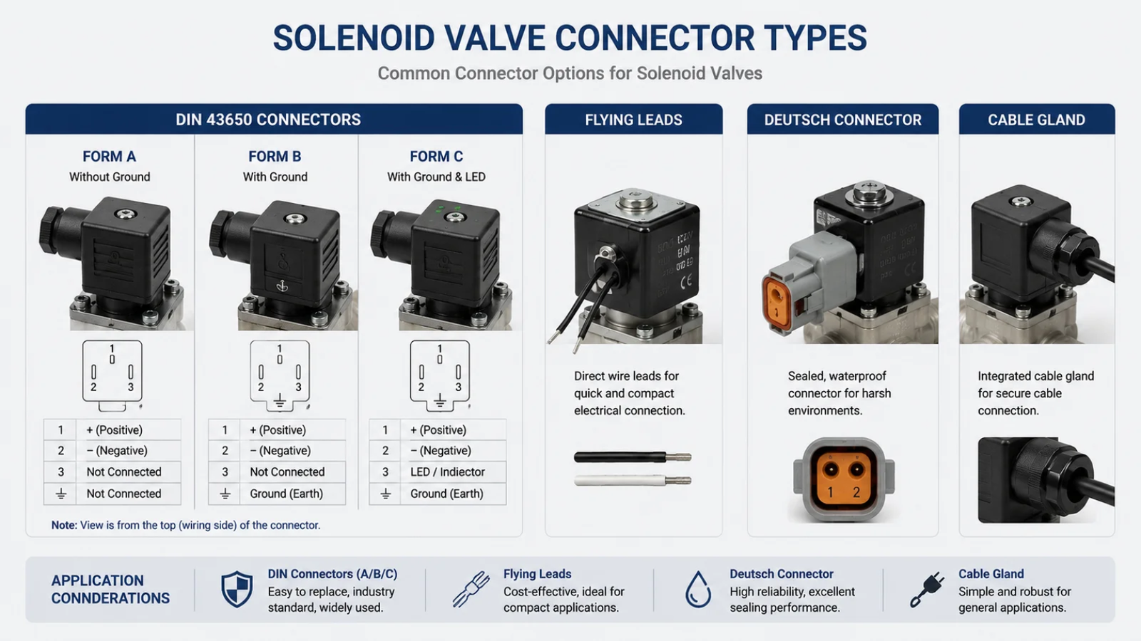
The most common solenoid valve connector types are standardized under DIN EN 175301-803 (formerly DIN 43650)2. These standards define the pin spacing and general shape, and the primary types are Form A, Form B, and Form C, each suited for different physical coil sizes and applications.
Dive Deeper
The DIN standards were created to ensure interoperability between valves and connectors from different manufacturers. While there are some industrial and micro-connectors outside this standard, these three forms cover the vast majority of applications you will encounter.
DIN 43650 Form A
Form A is the largest and most robust of the three. It has a distinctive square connector interface and features a pin spacing of 18 mm3. Because of its size, it is typically used with larger solenoid coils that require more power, making it a common choice for hydraulic presses, large pneumatic actuators, and heavy industrial machinery. Its U-shaped or flat gasket provides a wide sealing surface, offering excellent environmental protection.
DIN 43650 Form B
Form B is more compact, with a rectangular connector interface and two common pin spacings: 10 mm or 11 mm4. It strikes a balance between size and performance, making it popular in a wide range of industrial pneumatic systems and general automation equipment. It provides a reliable connection where space is more limited than what a Form A would allow.
DIN 43650 Form C
Form C is the smallest of the group, featuring a smaller square interface with pin spacings of 8 mm or 9.4 mm5. Its compact size makes it ideal for miniature pneumatic valves, compact sensors, and small appliances where space is at a premium. I've seen these used extensively in applications like coffee machines and medical devices, where every millimeter counts.
Here’s a quick comparison table:
| Feature | Form A | Form B | Form C |
|---|---|---|---|
| Pin Spacing | 18 mm | 10 mm or 11 mm | 8 mm or 9.4 mm |
| Shape | Square | Rectangular | Small Square |
| Typical Application | Hydraulics, large pneumatics | Industrial pneumatics | Compact pneumatics, small devices |
| Gasket Profile | U-shaped or flat | Flat | Flat |
What Are the 6 Factors to Consider Before Choosing a Connector?
You've matched the DIN form, so your job is done, right? Unfortunately, this is where many design and procurement teams go wrong. Ignoring these six other factors can lead to intermittent failures, high maintenance costs, and compromised product reliability.
Before selecting a solenoid valve connector, you must evaluate six key factors beyond its physical shape: electrical specifications, IP protection rating, circuitry options (like LEDs or surge suppression), housing material, cable entry size, and physical orientation.

Dive Deeper
A holistic approach is essential for long-term success. Let's break down each factor.
1. Electrical Specifications (Voltage & Current)
The connector must be rated for the voltage and current your solenoid coil requires. An underrated connector can overheat, melt, and become a fire hazard.6 Always check the manufacturer's datasheet for the maximum voltage (e.g., 24V, 120V, 230V) and current-carrying capacity (amperage).
2. Ingress Protection (IP) Rating
This is perhaps the most critical factor after form factor. The IP rating tells you how well the connector is sealed against solids (dust) and liquids (water).
- IP65: Protected against dust and low-pressure water jets from any direction.7 This is suitable for general factory environments.
- IP67: Protected against dust and temporary immersion in water (up to 1 meter for 30 minutes).8 This is a must for equipment that undergoes washdowns, like in food processing.
- IP69K: Protected against dust and high-pressure, high-temperature water jets.9 This is the gold standard for harsh environments where intensive cleaning is required.
3. Circuitry Options
Modern connectors can include built-in electronics that add significant value:
- LED Indicators: An LED provides instant visual confirmation that the valve is receiving power. This simple feature can save maintenance teams hours of troubleshooting time.
- Surge Suppression: When a solenoid coil de-energizes, it can create a high-voltage spike (inductive kickback).10 A surge suppression circuit, typically using a varistor (VDR) or diode, clamps this voltage spike, protecting sensitive control electronics like PLCs or microprocessors.11
4. Housing Material & Temperature Rating
The standard connector housing is made from Polyamide (PA), which is suitable for most applications. However, in environments with high ambient temperatures, UV exposure, or aggressive chemicals, you may need a connector made from a more resilient material. Always ensure the connector's operating temperature range matches your application.
5. Cable Entry & Gland Size
The cable gland must match your cable's outer diameter to create a proper seal.12 Common thread sizes for the gland include PG7, PG9, PG11, or metric sizes like M12 and M16. Using a gland that is too large for the cable will compromise the IP rating, allowing moisture and dust to enter.
H3: 6. Physical Orientation & Space
Connectors come in straight or 90-degree angled configurations. The choice depends on the available space and how you need to route the cable. In tight spaces, an angled connector can prevent sharp bends in the cable that could lead to damage over time.
How to Choose the Right Connector for Different Applications?
A solenoid valve connector that excels in a clean industrial automation setting will likely fail on a hydraulic press exposed to the elements. Using a one-size-fits-all approach leads to poor performance and reliability issues. So, how do you tailor your choice to the job?
Choosing the right solenoid valve connector requires prioritizing features based on the application's environment. For general industrial automation, a standard DIN connector may be adequate. However, for food equipment, a high IP rating is crucial, while hydraulic systems demand robustness and surge protection.

Dive Deeper
As a supplier to leading European brands, we help our clients navigate these choices daily. Here are some recommendations based on common applications:
Pneumatic Valves in Industrial Automation
On a busy assembly line, uptime is everything. Downtime for troubleshooting is extremely expensive.
- Priorities: Ease of maintenance, reliability.
- Recommendation: Use a DIN Form B or C connector with an integrated LED indicator. The LED allows technicians to see at a glance if a valve is getting power, dramatically speeding up diagnostics. A standard IP65 rating is usually sufficient for a typical dry factory environment.
Hydraulic Valves
Hydraulic systems operate under high pressure and often use large, powerful solenoid coils.
- Priorities: Robustness, vibration resistance, electrical protection.
- Recommendation: DIN Form A is the standard due to the larger coils. It's critical to choose a connector with built-in surge suppression (VDR). The large inductive kickback from a hydraulic coil can easily damage the output card of a PLC. Ensure the connector has a heavy-duty central screw to resist vibration.
Coffee Machines and Food Equipment
These applications involve moisture, heat, and strict regulations for cleanliness and safety.
- Priorities: High ingress protection, material safety, compact size.
- Recommendation: For equipment subject to frequent washdowns, a connector with an IP67 or IP69K rating is non-negotiable. This prevents water ingress during high-pressure cleaning. For something like a coffee machine, where internal steam and minor spills are a concern, IP65 might be sufficient, often using a compact DIN Form C connector. Materials should be corrosion-resistant—consider stainless steel screws.
What Are the Most Common Connector Selection Mistakes?
Even the most experienced engineers can make simple mistakes when specifying a connector. These seemingly small errors can compromise your entire system, leading to field failures and warranty claims. Are you guilty of any of these?
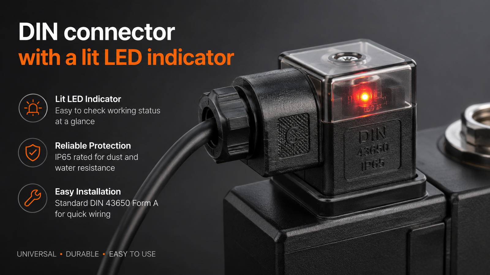
The most common mistakes in selecting a solenoid valve connector include ignoring the IP rating for the operating environment, forgetting to install the gasket, neglecting surge protection for inductive loads controlled by PLCs, and choosing a connector with the wrong cable gland size, all of which compromise the seal and electrical integrity.
Dive Deeper
Here are the mistakes I see most often in the field.
Focusing Only on Form Factor
This is the central theme of this article. Just because a Form B plug fits a Form B coil does not mean it's the right choice. The connector that works in a dry control cabinet is not the same one you should use on an outdoor mobile hydraulic system. Always consider the full environmental and electrical context.
Forgetting or Misusing the Gasket
The gasket is what creates the seal between the connector and the coil. I've personally reviewed field failures where a perfectly good IP67-rated connector failed because the installer forgot to place the gasket. Without it, the IP rating is completely void. Make sure the gasket is present, correctly seated, and not pinched during installation.
Skipping Surge Suppression
"It's just a 24VDC coil, it's fine." I hear this a lot. But when that coil is controlled by a sensitive PLC output card, the voltage spike on de-energization can be several hundred volts. This can cause erratic behavior or permanent damage to the controller. A connector with integrated surge suppression is a small price to pay to protect a component that costs ten times as much.
Mismatching the Cable Gland and Cable Diameter
Using a thin 4mm cable with a PG11 gland designed for 10-14mm cables is a recipe for failure. The rubber grommet in the gland cannot compress enough to create a seal, leaving a direct path for moisture and dust to enter the terminal housing. Always choose a connector with a cable gland range that matches your cable's outer diameter.
Frequently Asked Questions
Can I use a Form A connector on a Form B coil?
No, you cannot. The pin spacing and physical dimensions are completely different. A Form A connector has 18mm pin spacing, while a Form B has 10mm or 11mm. You must use a connector whose form factor matches that of the solenoid coil.
What does the LED on a solenoid valve connector indicate?
The LED light indicates that voltage is being supplied to the connector's terminals. It is an invaluable diagnostic tool. If the valve is not actuating but the LED is on, the problem is likely with the coil or the valve itself. If the LED is off, the problem is with the power supply or wiring.
Is surge suppression always necessary?
It is highly recommended whenever the solenoid is controlled by sensitive electronics, such as a PLC, microprocessor, or solid-state relay. For simple circuits controlled by a robust mechanical switch, it may not be as critical, but it is always a good practice to protect your system from voltage transients.
What is the difference between an IP65 and IP67 rating?
IP65 protects against low-pressure water jets from any direction, making it suitable for environments with splashing water. IP67 provides protection against temporary immersion in water up to 1 meter deep for 30 minutes. You should choose IP67 for any equipment that will be washed down or is at risk of being submerged.
Conclusion
Choosing the right solenoid valve connector is not a trivial task—it is a critical engineering decision that directly impacts the reliability and longevity of your equipment. Moving beyond a simple focus on DIN Form A, B, or C and embracing a holistic selection process is key. By carefully considering the electrical requirements, environmental conditions (IP rating), and the need for diagnostic or protective circuitry, you can prevent common failures and reduce long-term maintenance costs. This diligence ensures your product performs reliably in the field, protecting your brand's reputation for quality.
At SolenElec, we have over 20 years of OEM/ODM experience helping procurement managers and engineers at leading global brands select the right components. If you need a reliable partner for customized solenoid coils and connectors that guarantee long-term performance, contact our engineering team today to discuss your project.
Need Help Choosing the Right Solenoid Valve Connector?
The right connector is more than just the correct DIN form—it must match your application's electrical requirements, environmental conditions, and long-term reliability goals.
👉 Contact us to discuss your OEM project with our engineering team.
"(PDF) A Detailed Explanation of Solenoid Force", https://www.academia.edu/87099324/A_Detailed_Explanation_of_Solenoid_Force. A university engineering explanation of solenoids describes how current through a coil generates a magnetic field that produces motion in an actuator, supporting the article’s description of solenoid-valve actuation. Evidence role: mechanism; source type: education. Supports: Current through a solenoid coil produces a magnetic field that moves an actuator or plunger, enabling valve actuation.. Scope note: The source supports the electromechanical principle generally rather than the performance of any specific connector or valve assembly. ↩
"DIN connector", https://en.wikipedia.org/wiki/DIN_connector. The EN 175301-803 reference entry identifies the standard as the successor designation commonly associated with DIN 43650 electrical connectors used on solenoid valves. Evidence role: definition; source type: encyclopedia. Supports: EN 175301-803 is the standard associated with the industrial connector forms formerly known as DIN 43650.. Scope note: An encyclopedia source is a secondary summary; the formal DIN/EN standard remains the normative source for specifications. ↩
"Stecker-Typ C", https://de.wikipedia.org/wiki/Stecker-Typ_C. A technical reference on EN 175301-803 lists Form A connector contact spacing as 18 mm, corroborating the dimensional description in the article. Evidence role: definition; source type: encyclopedia. Supports: Form A connectors under the DIN 43650 / EN 175301-803 family are characterized by 18 mm contact spacing.. Scope note: The source should be treated as a secondary dimensional summary unless the official standard text is consulted. ↩
"DIN connector", https://en.wikipedia.org/wiki/DIN_connector. A technical reference on EN 175301-803 describes Form B connector variants with 10 mm and 11 mm contact spacing, supporting the article’s dimensional distinction. Evidence role: definition; source type: encyclopedia. Supports: Form B connectors in the DIN 43650 / EN 175301-803 family are commonly described with 10 mm or 11 mm pin spacing variants.. Scope note: The citation provides dimensional context from a secondary reference and does not replace the official standard for design validation. ↩
"How to Choose the Right DIN Connector Coil for Your ...", https://solenelec.com/how-to-choose-the-right-din-connector-coil-for-your-solenoid-valve/. A technical reference on EN 175301-803 lists Form C connector contact spacing variants of 8 mm and 9.4 mm, supporting the article’s description of the compact form. Evidence role: definition; source type: encyclopedia. Supports: Form C connectors are identified in technical summaries with 8 mm or 9.4 mm pin spacing variants.. Scope note: The source is best used for general dimensional corroboration; the formal standard should be consulted for controlled engineering specifications. ↩
"Controlling Electrical Hazards", https://www.osha.gov/sites/default/files/publications/OSHA3075.pdf. Government electrical-safety guidance identifies overloaded or improperly rated electrical equipment as a cause of overheating and fire risk, supporting the article’s warning about underrated connectors. Evidence role: general_support; source type: government. Supports: Electrical components operated beyond their rated capacity can overheat and create fire hazards.. Scope note: The source supports the general electrical-safety mechanism rather than documenting failures in solenoid valve connectors specifically. ↩
"IP code", https://en.wikipedia.org/wiki/IP_code. IEC 60529 defines the IP Code; the digit combination IP65 denotes dust-tight protection and protection against water jets, consistent with the article’s description. Evidence role: definition; source type: institution. Supports: Under the IEC IP Code, IP65 indicates complete protection against dust ingress and protection against water jets.. ↩
"IP code", https://en.wikipedia.org/wiki/IP_code. IEC 60529 defines IP67 as dust-tight protection with protection against temporary immersion in water under prescribed test conditions, commonly summarized as immersion up to 1 m for 30 minutes. Evidence role: definition; source type: institution. Supports: IP67 is defined as dust-tight protection plus protection against temporary immersion in water under specified conditions.. ↩
"IP code", https://en.wikipedia.org/wiki/IP_code. ISO 20653 and related IP69K descriptions define the rating as protection against dust ingress and close-range high-pressure, high-temperature water jets. Evidence role: definition; source type: institution. Supports: IP69K refers to protection against dust and high-pressure, high-temperature water-jet cleaning conditions.. Scope note: The rating describes performance under standardized tests and does not by itself guarantee suitability for every chemical washdown environment. ↩
"Snubber", https://en.wikipedia.org/wiki/Snubber. Engineering teaching materials on inductive loads explain that interrupting current through a coil can generate a high-voltage transient, often called inductive kickback or flyback voltage. Evidence role: mechanism; source type: education. Supports: Inductive loads can produce a voltage transient when current through the coil is interrupted.. Scope note: The source supports the general behavior of inductive coils rather than quantifying the voltage spike for a particular solenoid valve. ↩
"Flyback diode", https://en.wikipedia.org/wiki/Flyback_diode. Educational electronics references describe flyback diodes and varistors as suppression devices that limit voltage transients generated by inductive loads, supporting the article’s explanation of surge suppression. Evidence role: mechanism; source type: education. Supports: Flyback diodes and varistors are used to limit voltage transients from inductive loads.. Scope note: The source supports the protective principle; actual protection of a PLC depends on circuit design, ratings, wiring, and the transient energy involved. ↩
"Cable gland", https://en.wikipedia.org/wiki/Cable_gland. Institutional guidance on cable glands explains that glands are selected according to the cable outside diameter so that the sealing element can compress properly and maintain ingress protection. Evidence role: mechanism; source type: institution. Supports: Cable glands are specified by cable diameter range because correct compression around the cable is necessary for sealing and strain relief.. Scope note: The source supports the general sealing requirement; the achieved IP rating also depends on installation torque, gasket condition, enclosure design, and testing. ↩