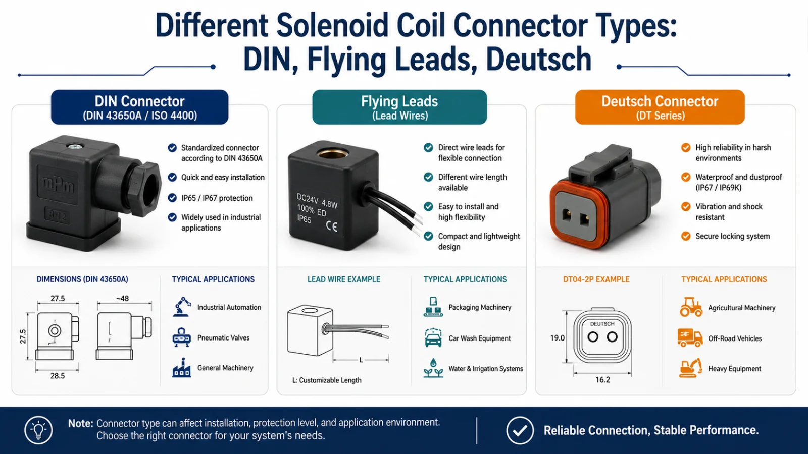
DIN 43650 Form A vs B vs C: How to Choose the Right Solenoid Coil Connector?
DIN 43650 connector selection can become a problem when a valve, coil, and cable connector appear similar but do not mate correctly. I often see engineers and buyers focus on voltage first, then discover that the physical interface, pin spacing, or sealing arrangement does not match. A structured comparison prevents avoidable design and sourcing delays.
DIN 43650 Form A, Form B, and Form C connectors are not generally interchangeable because they use different mechanical interfaces, pin spacing arrangements, and physical envelopes.1 Engineers should select the form that matches the valve or solenoid coil mating interface, then verify voltage, coil power, duty cycle, environmental protection, and any LED or surge-suppression requirements.

I treat the connector form as the starting point, not the complete specification. DIN compliance can help define a connector interface, but it does not prove that two solenoid coils will perform the same way on a specific valve.2 The sections below explain how I would evaluate the interface and build a complete OEM coil specification.
DIN 43650 Form A vs B vs C: What Is the Quick Comparison?
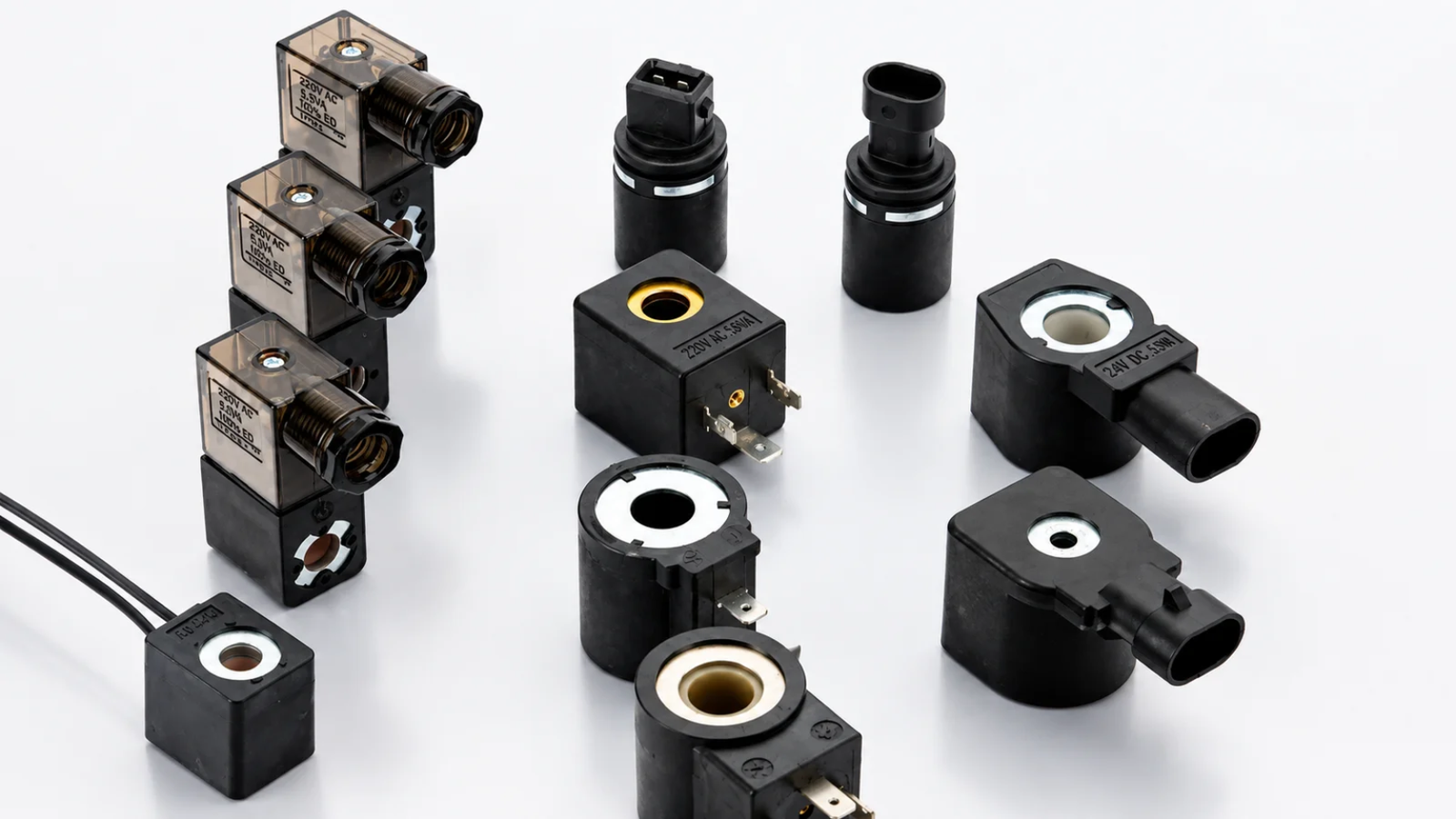
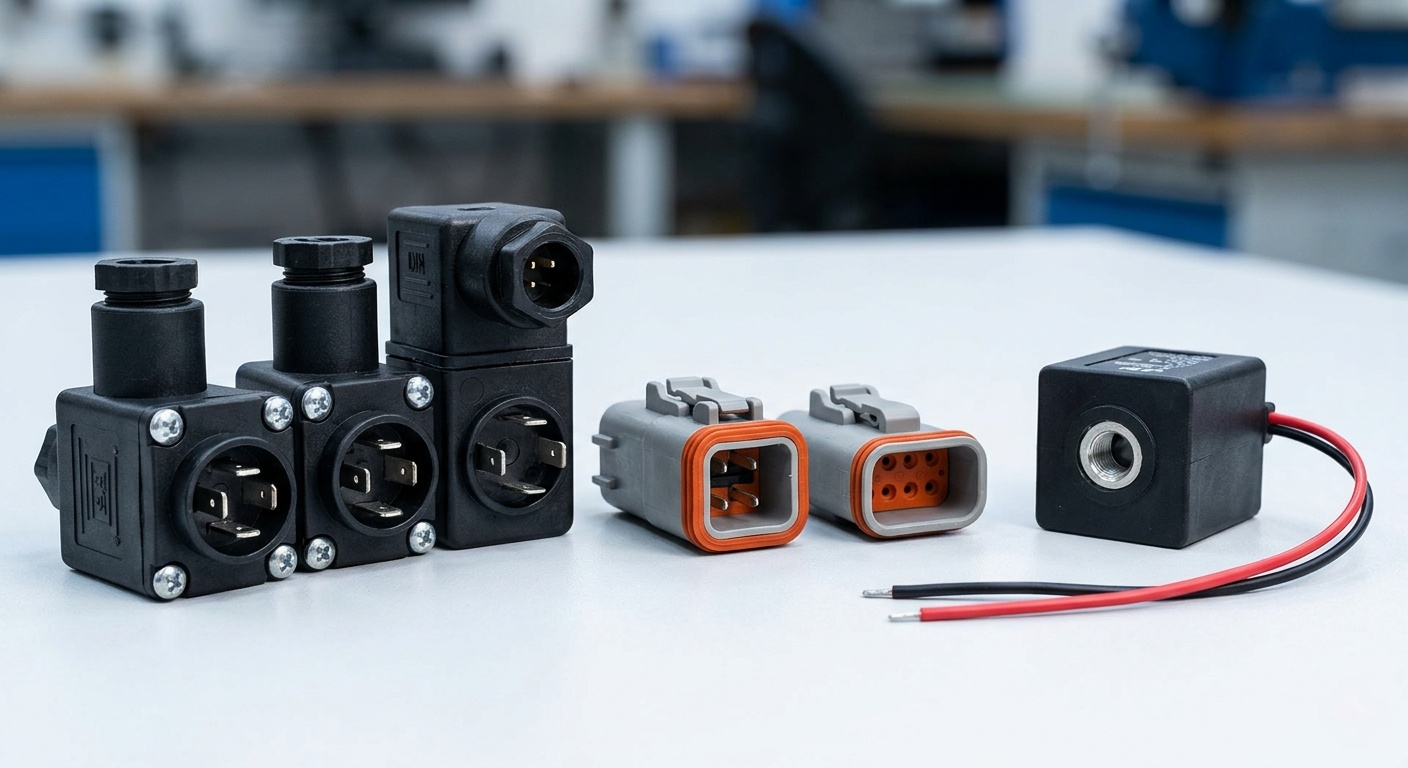
A DIN solenoid connector may look like a simple three-pin component, but the wrong form can stop assembly immediately. The risk becomes greater when an OEM project involves multiple valve families, several suppliers, or incomplete legacy drawings. I recommend comparing the mechanical interface before comparing electrical features.
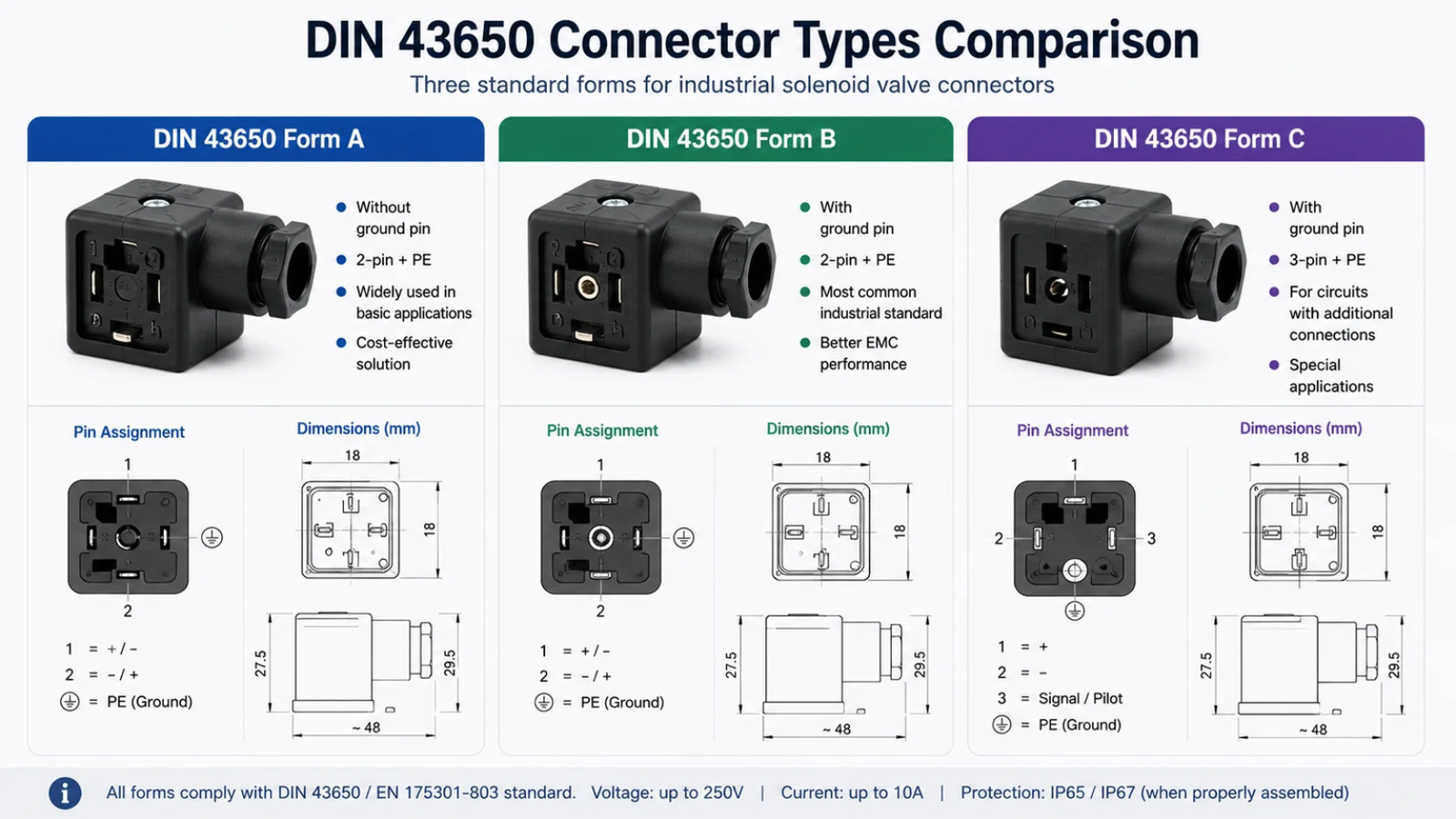
Form A, Form B, and Form C differ mainly in connector geometry, pin spacing, mating footprint, and physical size. Form A is generally the largest interface, Form C is generally more compact, and Form B requires particular care because 10 mm and 11 mm variants may exist.3 A 24 VDC rating does not make the forms compatible.

DIN 43650 Form A, B, and C Comparison Table
| Parameter | Form A | Form B | Form C |
|---|---|---|---|
| General physical envelope | Usually the largest of the three common forms | Intermediate but variant-dependent | Usually the most compact common form |
| Pin spacing | Verify against the applicable standard and coil datasheet | Must verify, especially 10 mm vs 11 mm variants | Verify against the applicable standard and coil datasheet |
| Typical connector footprint | Larger rectangular footprint | Smaller than Form A, with geometry that needs exact confirmation | Compact footprint for space-constrained equipment |
| Mating interface | Must match Form A coil or valve interface | Must match the correct Form B interface and spacing | Must match Form C coil or valve interface |
| Common evaluation context | Larger industrial valve and actuator assemblies | Valve and coil designs requiring the Form B interface | Compact pneumatic, hydraulic, and control equipment designs |
| Interchangeable with other forms? | No | No | No |
| Electrical options | May be available with LED, diode, VDR, or plain wiring | May be available with LED, diode, VDR, or plain wiring | May be available with LED, diode, VDR, or plain wiring |
Why the Interface Comes Before the Voltage
In my experience, buyers sometimes send an inquiry that says only: “24VDC DIN coil required.” That information is useful, but it does not identify a complete part. A 24 VDC coil may have a Form A, Form B, or Form C connection. It may also have a flying lead, molded cable, terminal box, or another electrical interface.
I use this decision order:
- Identify the mating connector form from the valve or coil drawing.
- Confirm pin spacing and mechanical dimensions, especially for DIN Form B.
- Confirm electrical requirements, including voltage, AC or DC supply, wattage, VA, and duty cycle.
- Check the operating environment, including moisture, dust, vibration, ambient temperature, and chemical exposure.
- Select functional connector options, such as an LED indicator, rectifier, diode, or varistor.
- Validate the valve and magnetic interface, including bore size, armature tube dimensions, force requirement, and thermal performance.
Engineering reminder: A DIN connector form describes an interface. It does not automatically define coil wattage, magnetic force, insulation class, or duty-cycle capability.
This distinction matters in OEM sourcing. Two coils can both use a DIN 43650 connector and still differ in dimensions, resistance, thermal behavior, encapsulation, or valve compatibility. I would always ask for a drawing, existing sample, or valve-interface data before approving a substitution.
What Is DIN 43650 / EN 175301-803?
Engineers still use “DIN 43650” in everyday discussions, catalogs, and purchase orders. However, a project team can become confused when a newer drawing refers to EN 175301-803 instead. I find that a short explanation helps prevent teams from treating these names as unrelated connector systems.
DIN 43650 is a widely used industry name for rectangular electrical connectors commonly used with solenoid valves and coils.4 EN 175301-803 is the later European standard designation associated with these connector interfaces.5 In practical sourcing, engineers should verify the exact applicable document, form, dimensions, and product datasheet.

Why Both Names Still Appear
The term DIN 43650 remains common because it is deeply established in industrial automation, pneumatic controls, hydraulic systems, and solenoid valve documentation. Many engineers, distributors, and maintenance teams use it as a practical shorthand for the familiar rectangular connector family.
EN 175301-803 is commonly used in newer technical references. Depending on the product, a manufacturer may also use a form designation, a drawing number, or a proprietary connector description alongside the standard reference.
For procurement and engineering purposes, I would avoid assuming that a standard name alone is enough. A reliable specification should include:
- Connector form: A, B, or C
- Pin arrangement and spacing
- Number of contacts
- Ground-contact requirement
- Cable-entry orientation and thread type, where relevant
- Rated voltage and current
- Required ingress protection after assembly
- LED or surge-protection configuration
- Mating coil or valve drawing
What the Standard Does—and Does Not—Solve
A connector standard helps establish a common mechanical and electrical connection approach. This can simplify replacement planning, cable assembly selection, and integration into industrial equipment.
However, the connector standard does not define the entire solenoid coil system. It does not automatically determine:
| Selection Area | Why It Still Requires Verification |
|---|---|
| Coil bore and height | The coil must fit the armature tube or valve structure |
| Electrical rating | Voltage alone does not define resistance, power, or inrush behavior |
| Thermal design | Ambient temperature, duty cycle, and enclosure affect coil temperature |
| Magnetic performance | The coil must generate suitable force for the valve design |
| Sealing performance | IP performance depends on the complete assembled system |
| Suppression circuit | Diodes and varistors affect control behavior differently |
I see the DIN 43650 interface as one layer of a larger engineering decision. It is an important layer, but it should not replace a complete application review.
DIN 43650 Form A: When Should Engineers Use It?
A larger connector can offer a familiar and practical interface, but engineers should not choose it simply because it looks more robust than another form. The valve or coil design normally dictates the mating connection. A mismatch can create mounting problems, sealing problems, or an immediate inability to connect.
DIN 43650 Form A should be used when the solenoid coil or valve has a matching Form A mating interface and the available installation space supports its physical envelope. Engineers should verify the connector drawing, terminal arrangement, cable exit direction, environmental requirement, and complete coil specification before final selection.

Form A Is an Interface Choice
Form A is commonly recognized as the larger member of the familiar DIN connector family. Its physical footprint can suit equipment where space allows a larger connector body and where the valve manufacturer has designed the coil or valve around that interface.
Still, I do not describe Form A as automatically “high power.” A coil’s power requirement depends on the electromagnetic design, voltage, resistance, valve function, duty cycle, and thermal limits. A compact coil can have demanding thermal requirements, while a larger coil may operate at modest electrical power.
What I Check Before Selecting Form A
For a Form A project, I would confirm the following points:
- Mating-face drawing: The valve or coil must have the matching interface.
- Terminal configuration: Confirm the number and position of electrical contacts.
- Protective earth connection: Verify whether the application requires it.
- Cable outlet direction: Straight and angled cable entries can affect installation clearance.
- Voltage and supply type: Confirm 12 VDC, 24 VDC, 48 VDC, 110 VAC, 230 VAC, or another requirement.
- Connector function: Decide whether a plain connector, LED connector, diode connector, or VDR connector is needed.
- Ingress protection target: Evaluate the fully assembled connector, seal, screw, cable, and coil system.
- Service access: Leave sufficient room for installation, removal, and cable bending.
A Practical Integration Example
I have seen projects where a Form A connector technically fit the valve but created a packaging conflict after the enclosure was assembled. The coil and connector were correct in isolation, yet the cable exit direction interfered with a nearby manifold or machine panel.
That issue is why I recommend reviewing the installed envelope, not only the connector face. The engineering drawing should show:
- Coil dimensions.
- Connector dimensions.
- Cable-gland dimensions.
- Cable bend radius.
- Screw-access clearance.
- Nearby mechanical obstructions.
A Form A DIN solenoid connector can be an appropriate solution when it matches the existing valve architecture. The selection should follow the mating interface and system layout, rather than a general assumption about power level.
DIN 43650 Form B: Why Do 10 mm vs 11 mm Variants Matter?
Form B creates one of the most common specification risks in DIN connector sourcing. Teams may correctly identify “Form B” but still receive a connector or coil that does not mate with the existing part. This problem often appears in replacement orders, legacy equipment, and OEM programs with incomplete documentation.
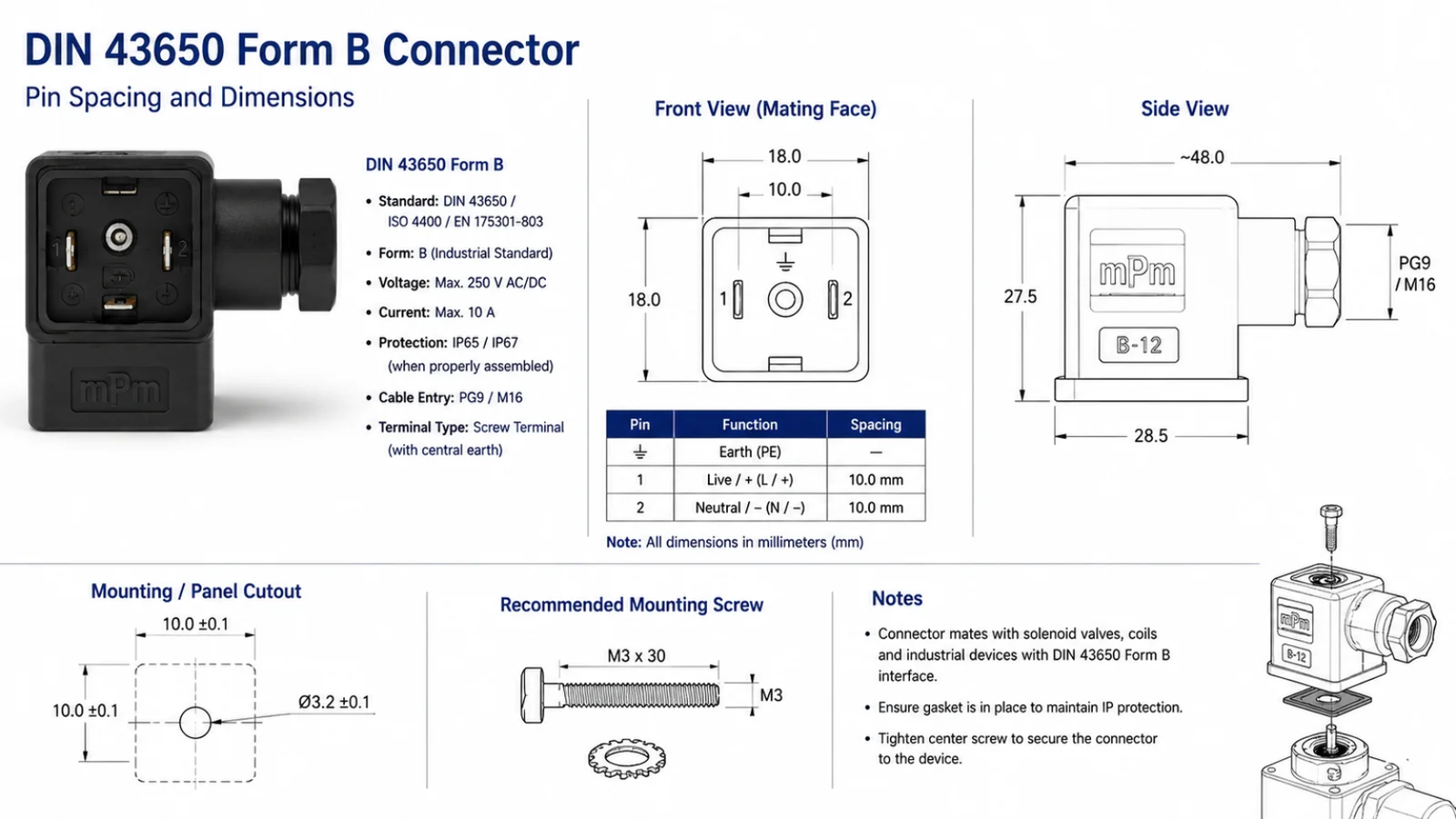
DIN 43650 Form B may involve 10 mm or 11 mm pin-spacing variants, and these variants should not be assumed interchangeable. Engineers must confirm the actual mating interface by drawing, datasheet, measurement, or approved sample. Specifying only “DIN Form B” is not enough for many OEM orders.

Why Form B Needs Extra Verification
The phrase “DIN Form B” sounds precise, but it can hide a critical dimensional detail. In the market, engineers may encounter Form B connector arrangements associated with 10 mm or 11 mm spacing. Even a 1 mm difference can prevent proper mating.6
The connector may look nearly identical during a visual inspection. However, the sealing surface, contact location, housing geometry, or screw alignment can differ enough to create problems.
Important OEM warning: “DIN Form B” alone may not provide enough information for an OEM order. I would always confirm the mating interface and pin spacing.
How I Confirm 10 mm vs 11 mm Form B Requirements
I use the following hierarchy of evidence:
- Original valve or coil drawing from the equipment manufacturer.
- Approved connector drawing showing contact-center dimensions.
- Datasheet part number that identifies the exact interface.
- Physical measurement of an existing approved component.
- Sample fit test before mass production.
A caliper measurement can support the review, but I would not rely on a quick measurement alone if a controlled drawing is available. Molded housings, gasket compression, and measurement reference points can make informal checks less reliable.
What Can Go Wrong if the Spacing Is Incorrect?
An incorrect Form B selection can lead to several outcomes:
- The connector cannot be installed.
- The contacts do not align correctly.
- The gasket does not seal as intended.
- The screw cannot secure the connector properly.
- The assembly appears to fit but experiences intermittent electrical contact.
- The wrong part reaches a production line and delays final assembly.
These risks are especially relevant for high-volume appliance or industrial-equipment programs. A low-cost connector mismatch can become expensive when it interrupts a controlled assembly process.
Form B Specification Example
A better purchase description would look like this:
| Incomplete Description | Better Engineering Description |
|---|---|
| 24VDC DIN Form B coil | 24 VDC solenoid coil with confirmed Form B mating interface, 11 mm pin spacing, specified coil bore, power rating, duty cycle, IP requirement, and LED/diode configuration |
| Form B connector | Form B cable connector with confirmed 10 mm mating spacing, cable entry type, gasket, screw, IP target after assembly, and required suppression circuit |
I consider this level of detail essential when a coil is being developed or qualified for an OEM program.
DIN 43650 Form C: When Is the Compact Interface Better?
Compact equipment often creates pressure to reduce the space around valves, manifolds, and cable assemblies. However, a smaller DIN connector should not be selected solely because it saves space. The matching coil and valve interface must support it, and the total electrical and environmental requirements still need review.
DIN 43650 Form C is often suitable when a valve or solenoid coil uses the matching compact Form C interface and the equipment layout benefits from a smaller connector envelope. Engineers should still verify pin geometry, installation clearance, cable routing, voltage, coil thermal performance, and required protection features.

Where a Compact Interface Helps
Form C is generally associated with a more compact physical interface than Form A.7 This can be useful in equipment where several valves are grouped closely together or where the available wiring area is limited.
For example, a compact interface may be considered in:
- Pneumatic valve islands
- Compact hydraulic control assemblies
- Small process-control devices
- Space-constrained appliance mechanisms
- Equipment with closely spaced solenoid valves
- Modules where cable routing must remain controlled
These are application contexts, not absolute rules. I would not assume that every pneumatic valve uses Form C or that every Form C coil has a low power requirement. The actual coil design remains application-specific.
Compact Size Changes the Integration Review
When the connector footprint is smaller, the installation details can become more important. I would check:
- Whether adjacent connectors can be installed and removed without interference
- Whether the cable can bend without stressing the gland or conductor
- Whether the connector screw remains accessible
- Whether the cable exit orientation blocks another component
- Whether the required IP level can be achieved after assembly
- Whether an LED or suppression component increases the connector body size
- Whether heat from nearby coils affects the duty-cycle calculation
Form C and Coil Performance Are Separate Decisions
A Form C connector identifies a compact electrical interface. It does not independently define:
- Coil operating temperature
- Pull-in or holding force
- AC inrush behavior
- DC resistance
- Power consumption
- Continuous-duty suitability
- Valve compatibility
This separation is important in OEM coil design. A customer may need a compact external interface while also requiring a coil that withstands a specific ambient temperature, operating cycle, and voltage tolerance. The engineering solution must satisfy both the connector interface and the electromagnetic requirements.
In my approach, Form C is the right choice when the existing mating interface requires it and when the compact installation envelope supports the wider system design.
Are DIN 43650 Form A, B, and C Interchangeable?
Interchangeability is the question I hear most often when a buyer has a 24 VDC coil in hand and needs a replacement quickly. The similar appearance of these connector families can create false confidence. A matching voltage label does not correct a mechanical mismatch.
No, DIN 43650 Form A, Form B, and Form C connectors are not generally interchangeable. They have different connector geometry, pin spacing, mating dimensions, and physical envelopes. Even if two coils have the same voltage, their connectors may not mate, seal, mount, or provide the required electrical function.

Why Voltage Does Not Establish Compatibility
Voltage tells me what electrical supply a coil is designed to use. It does not tell me:
- Which connector will physically fit
- Whether terminals align
- Whether the coil bore fits the valve armature tube
- Whether the coil generates the needed magnetic force
- Whether the coil can run at the intended duty cycle
- Whether the assembly achieves the required ingress protection
- Whether the control circuit needs a diode or varistor
A 24 VDC Form A coil and a 24 VDC Form C coil may share the same nominal supply voltage, yet they can be completely incompatible mechanically and functionally.8
Common OEM Mistake: Specifying Only “24VDC DIN Coil”
A common incomplete request is:
“We need a 24VDC DIN coil for our solenoid valve.”
I would treat this as a starting point for clarification, not as a production-ready specification. The supplier still needs to know the connector form, physical dimensions, valve interface, power requirement, operating cycle, insulation requirement, and environmental conditions.
Compatibility Checklist
Before approving a replacement or custom solenoid coil, I recommend verifying:
| Compatibility Item | Question to Ask |
|---|---|
| Connector form | Is the required interface Form A, B, or C? |
| Form B spacing | If Form B, is it 10 mm or 11 mm? |
| Coil bore | Does the bore fit the valve armature tube? |
| Coil height and width | Does the coil fit the installed envelope? |
| Voltage and supply | Is the system AC or DC, and what tolerance applies? |
| Power requirement | What wattage or VA is needed for the valve design? |
| Duty cycle | Is the coil intermittent, continuous, or pulse-operated? |
| Electrical protection | Is LED, diode, VDR, or external suppression required? |
| Environmental protection | What IP rating is required after installation? |
DIN compliance solves the connector-interface problem. It does not automatically guarantee that two solenoid coils are functionally interchangeable. I would always validate mechanical fit, electrical rating, thermal design, environmental protection, and magnetic interface together.
Does the DIN 43650 Connector Determine IP65 or IP67 Protection?
Ingress protection is often reduced to a single catalog phrase such as “DIN connector IP65.” That phrase can be useful, but it can also be misleading when teams assume the connector alone controls the final protection level. In real equipment, the assembled condition matters.
No, the DIN 43650 connector name alone does not determine whether an assembly achieves IP65 or IP67 protection. The final IP performance depends on the connector housing, gasket, fixing screw, cable gland, cable diameter, coil encapsulation, mating surface, assembly torque, and actual installation conditions.

IP Rating Is a System-Level Result
An IP rating describes protection against ingress under defined test conditions.9 The result applies to a tested configuration, not necessarily to every possible installation using the same connector family.
For a DIN solenoid connector assembly, I would examine:
- Connector housing: The molded body must be suitable for the intended environment.
- Gasket: The gasket must match the mating surface and remain properly positioned.
- Fixing screw: The screw must secure the connector with appropriate compression.
- Cable gland: The gland must match the cable diameter and be installed correctly.
- Cable condition: A damaged or undersized cable can compromise sealing.
- Coil encapsulation: The coil body must support the targeted environmental resistance.
- Mating surface: A damaged, uneven, or contaminated coil face can reduce sealing performance.
- Installation direction: Standing water, washdown exposure, vibration, and cable tension can change field performance.
IP65 vs IP67 in Practical Evaluation
| Rating | General Meaning | Practical Engineering Question |
|---|---|---|
| [IP65 | Dust-tight protection and resistance to water jets under defined conditions](https://solenelec.com/how-to-improve-solenoid-valve-reliability-in-water-treatment-systems/)%%%FOOTNOTE_REF_10%%% | Will the gasket, cable gland, and installed orientation withstand washdown or spray exposure? |
| IP67 | Dust-tight protection and temporary immersion resistance under defined conditions | Is the complete assembly tested and suitable for temporary immersion in the actual application? |
I would not assume that a connector sold as IP67 makes every coil assembly IP67. The coil housing, sealing interface, cable entry, and installation process must support that claim.
How I Specify Environmental Requirements
For an OEM project, I would include both the required rating and the operating context:
- Target IP rating after final assembly
- Indoor, outdoor, washdown, splash, or temporary-immersion exposure
- Ambient temperature range
- Presence of oil, cleaning agents, humidity, or salt mist
- Vibration and cable movement
- Expected service life and maintenance practice
Where certifications or test reports are important, buyers should request and verify the relevant documents for the exact product configuration. A general statement about a connector family is not a substitute for evidence tied to the supplied part.
Should You Choose an LED, Diode, Varistor, or No Suppression?
A solenoid coil is an inductive load. When DC current is switched off, the stored magnetic energy can produce a voltage transient that affects relays, PLC outputs, transistors, and other control components. At the same time, adding suppression can change release behavior and wiring requirements.
Engineers should choose LED, diode, varistor, or no built-in suppression based on the control circuit and diagnostic needs. LEDs help show coil status, diodes provide effective DC transient suppression but require correct polarity and can slow release, while varistors offer bidirectional clamping with characteristics that must match the application.

Connector Protection Options Compared
| Option | Typical Use | Main Advantage | Engineering Consideration |
|---|---|---|---|
| LED indicator | Status indication and maintenance diagnostics | Provides visible confirmation that voltage is present | LED circuit must match voltage and polarity requirements |
| Diode | DC solenoid coils | Strong suppression of inductive voltage spikes | Polarity matters; coil release time may increase |
| Varistor / VDR | AC or DC designs depending on circuit configuration | Bidirectional transient suppression | Clamping voltage and energy capability need review |
| No built-in suppression | Simple circuits or systems with external protection | Lower connector complexity | External circuit protection may still be necessary |
When an LED Is Useful
An LED connector can help maintenance teams identify whether a coil is receiving electrical power. I find it useful during commissioning and fault finding, especially when several valves are installed on a manifold.
However, an LED only indicates that voltage is present at the connector. It does not prove that:
- The coil is electrically healthy
- The valve spool or armature is moving
- The fluid or air path is open
- The coil has adequate magnetic force
- The valve is free from contamination
When a Diode Is Appropriate
For many DC coil applications, a diode can reduce switching transients effectively. The trade-off is that the coil current decays more slowly after switch-off, which can delay valve release. That delay may be acceptable in some systems and unacceptable in fast-response applications.
I would confirm:
- DC supply voltage and polarity.
- Required release time.
- Type of PLC or transistor output.
- Whether the controller already includes suppression.
- Whether a reversed connection is possible during field service.
When a Varistor May Be Better
A varistor, also called a VDR, can provide bidirectional transient suppression. This may be useful where polarity-sensitive diode suppression is not appropriate or where a different release-time behavior is desired. The clamping characteristics must be evaluated against the circuit voltage and expected transient energy.
The correct choice is not “always add suppression.” The correct choice is to understand the coil, switching device, wiring length, response-time requirement, and existing control protection.
How Should You Specify a DIN 43650 Solenoid Coil for an OEM Project?
OEM coil projects often fail at the quotation stage because the request contains only a voltage and a connector name. That information may identify a general product family, but it does not give an engineer enough data to validate fit, performance, or long-term operating conditions.
For an OEM DIN 43650 solenoid coil project, engineers should specify the connector form, mating interface, mechanical dimensions, voltage, AC or DC supply, power requirement, duty cycle, insulation class, IP target, protection circuit, valve interface, application conditions, and expected annual quantity. Voltage and DIN form alone are not enough to guarantee compatibility or reliability.

OEM Solenoid Coil Engineering Checklist
I recommend collecting the following information before requesting a quotation, sample, or design review.
| Specification Item | Why It Matters |
|---|---|
| Connector form: A, B, or C | Defines the required electrical mating interface |
| Pin spacing and mating drawing | Critical for Form B and all mechanical fit checks |
| Coil bore and armature-tube dimensions | Determines valve compatibility |
| Coil outer dimensions | Confirms installed space and connector clearance |
| Voltage | Defines the nominal electrical supply |
| AC or DC | Changes coil design and control considerations |
| Frequency for AC coils | Important for 50 Hz, 60 Hz, or specific supply conditions |
| Power requirement | Supports electromagnetic and thermal design |
| Duty cycle | Determines heating and continuous-operation suitability |
| Insulation class | Helps evaluate temperature capability |
| Ambient temperature | Affects coil temperature rise and material selection |
| IP requirement | Guides sealing and assembly evaluation |
| LED, diode, or varistor | Defines diagnostic and transient-suppression functions |
| Valve and armature interface | Ensures the coil works with the intended valve mechanism |
| Application medium and environment | Identifies exposure to moisture, oil, chemicals, vibration, or heat |
| Annual quantity | Supports tooling, capacity, sourcing, and quality-planning decisions |
A Better Way to Start an OEM Inquiry
A practical inquiry package may include:
- Existing coil photos from several angles
- Coil, connector, and valve drawings
- Part number and current supplier datasheet, if available
- Electrical test requirements
- Environmental and IP targets
- Required certifications or compliance documents for buyer verification
- Sample quantity and project timeline
- Estimated annual volume
- Packaging and labeling requirements
The Core Engineering Decision
For OEM projects, I use one clear principle:
Specifying only voltage and DIN form is not enough to guarantee compatibility or long-term reliability.
The final coil must satisfy six connected requirements:
- Mechanical fit
- Electrical rating
- Thermal design
- Duty-cycle capability
- Environmental protection
- Magnetic and valve-interface performance
At SolenElec, we can review these factors for OEM and customized solenoid coil projects. Our engineering review can consider voltage, power, duty cycle, dimensions, insulation, connector configuration, and operating environment before a design moves toward prototyping or production. Buyers should still perform qualified application-specific validation in their own equipment.
Frequently Asked Questions
Can I replace a DIN 43650 Form A connector with a Form B connector?
No. DIN 43650 Form A and Form B use different mechanical interfaces and are not generally interchangeable. I recommend confirming the existing coil or valve drawing, connector footprint, contact arrangement, and mating dimensions before ordering a replacement.
Are DIN 43650 Form B 10 mm and 11 mm connectors interchangeable?
No, they should not be assumed interchangeable. The 10 mm and 11 mm Form B variants can differ in contact spacing and mating geometry. I recommend verifying the exact dimension from a technical drawing, manufacturer datasheet, approved sample, or controlled physical measurement.
Does a DIN connector with an LED protect the PLC output from coil voltage spikes?
Not necessarily. An LED mainly provides status indication. Protection from inductive voltage spikes typically requires a diode, varistor, or suitable external suppression circuit. I would review the control output type, voltage, polarity, and required valve release time before selecting a protection option.
Does an IP67 DIN 43650 connector make the whole solenoid coil assembly IP67?
No. The final protection rating depends on the complete assembly, including the connector, gasket, fixing screw, cable gland, cable diameter, coil encapsulation, mating face, and installation quality. Buyers should verify test documentation for the exact assembled configuration.
What information should I send for a custom DIN solenoid coil quotation?
I recommend sending the connector form, pin spacing, coil dimensions, bore size, voltage, AC or DC supply, power or VA requirement, duty cycle, insulation class, ambient temperature, IP target, protection option, valve details, application conditions, drawings, photos, and expected annual quantity.
Conclusion
DIN 43650 Form A, Form B, and Form C connectors should be selected by the required mating interface, pin spacing, physical envelope, and installation conditions—not by assumptions about coil power. I would give special attention to the 10 mm versus 11 mm DIN Form B distinction and remember that matching voltage does not make coils interchangeable. For OEM and custom solenoid coil projects, SolenElec can review your application specifications, drawings, and operating conditions to help evaluate a suitable connector and coil configuration.
"Type 2516 - Cable plug, form C according to DIN EN 175301-803", https://www.burkert-usa.com/en/type/2516. A standards source for DIN 43650 or EN 175301-803 identifies form-specific rectangular connector interfaces and dimensions, supporting the statement that Forms A, B, and C should not be treated as mechanically interchangeable. Evidence role: definition; source type: institution. Supports: A standards or standards-catalog source should show that the connector forms are defined by distinct mechanical interfaces and dimensions.. Scope note: The standard can support the formal interface differences, but it does not prove incompatibility for every proprietary or modified connector design. ↩
"Plug-in vs Flying Lead Solenoid Coils: Which Is Better for 4V210 ...", https://solenelec.com/plug-in-vs-flying-lead-solenoid-coils-which-is-better-for-4v210-pneumatic-valves/. Engineering references on solenoid coils describe performance as depending on coil geometry, current, magnetic circuit, heating, and duty cycle, supporting the distinction between connector-interface compliance and valve-level functional equivalence. Evidence role: mechanism; source type: education. Supports: A technical education or engineering source should explain that solenoid coil performance depends on electromagnetic, thermal, and mechanical design variables beyond the connector interface.. Scope note: Such sources provide general engineering context rather than direct testing of the specific DIN connector forms discussed in the article. ↩
"DIN 43650 Form A, Form B, Form C Comparison Chart", https://www.productsforautomation.com/din-43650-connector-characteristics-a/301.htm. Dimensional references for DIN 43650 or EN 175301-803 connector forms support the general distinction between larger Form A, compact Form C, and Form B spacing variants, including 10 mm and 11 mm arrangements. Evidence role: general_support; source type: institution. Supports: A standards-based dimensional reference should support the relative form sizes and the existence of Form B spacing variants.. Scope note: Relative size descriptions are contextual and may vary with housing style, cable gland, or manufacturer-specific packaging. ↩
"How to Choose the Right DIN Connector Coil for Your Solenoid ...", https://solenelec.com/how-to-choose-the-right-din-connector-coil-for-your-solenoid-valve/. Standards references for DIN 43650 and EN 175301-803 describe rectangular electrical connector interfaces associated with solenoid-valve applications, supporting the article's definition of the connector family. Evidence role: definition; source type: institution. Supports: A standards catalogue or technical standards source should identify DIN 43650 or EN 175301-803 as relating to rectangular connectors used for solenoid valves.. Scope note: A formal standards source supports the technical meaning of the designation, but it may not quantify how widely the older DIN name remains used in industry. ↩
"Top 10 DIN Connector Manufacturers for Industrial Automation in 2026", https://solenelec.com/top-10-din-connector-manufacturers-for-industrial-automation-in-2026-how-engineers-should-evaluate-them/. Standards documentation and catalogues identify EN 175301-803 as the European standard associated with the rectangular connector interfaces historically referred to as DIN 43650. Evidence role: historical_context; source type: institution. Supports: A standards organization or standards catalogue should support the relationship between the older DIN 43650 designation and EN 175301-803.. Scope note: The source may establish the standards relationship without documenting every legacy catalogue or purchasing usage. ↩
"What Are Solenoid Coil Connectors and How Do They Affect ...", https://solenelec.com/what-are-solenoid-coil-connectors-and-how-do-they-affect-performance-and-reliability/. Connector-design references describe mating reliability as dependent on contact alignment and mechanical tolerances, supporting the article's warning that a 1 mm spacing mismatch can prevent proper mating or reliable contact. Evidence role: mechanism; source type: education. Supports: A connector-design reference should explain that mating connectors require aligned contact geometry within specified tolerances.. Scope note: This provides general mechanical support rather than test data for a specific DIN Form B connector pair. ↩
"How to Choose the Right Solenoid Valve Connector for Your ...", https://solenelec.com/how-to-choose-the-right-solenoid-valve-connector-for-your-application/. Dimensional references for DIN 43650 or EN 175301-803 connector forms support the general characterization of Form C as a more compact interface than Form A. Evidence role: general_support; source type: institution. Supports: A dimensional standards reference should support the general size difference between Form A and Form C connector interfaces.. Scope note: The statement is comparative at the interface level; complete connector assemblies may differ in size depending on housing, cable-entry, and accessory options. ↩
"Pneumatic Solenoid Coils: How Do You Select the Right Coil for ...", https://solenelec.com/pneumatic-solenoid-coils-how-do-you-select-the-right-coil-for-your-valve/. Solenoid coil selection references identify voltage as only one rating among mechanical fit, coil power, duty cycle, thermal limits, and valve interface, supporting the claim that equal nominal voltage does not establish interchangeability. Evidence role: general_support; source type: education. Supports: A solenoid coil selection reference should show that compatibility requires checking voltage along with dimensions, power, duty cycle, and valve interface.. Scope note: The support is general selection guidance and does not compare the specific Form A and Form C examples experimentally. ↩
"IEC 60529 Ingress Protection (IP Code) Certification Testing", https://keystonecompliance.com/iec-60529/. IEC 60529 defines IP codes as classifications of enclosure protection against ingress of solid objects and water under specified test conditions, supporting the article's explanation of IP ratings. Evidence role: definition; source type: institution. Supports: An IEC or standards-based source should define IP ratings as classifications of protection against solid-object and water ingress under specified tests.. ↩
"How to Improve Solenoid Valve Reliability in Water Treatment ...", https://solenelec.com/how-to-improve-solenoid-valve-reliability-in-water-treatment-systems/. IEC 60529 classifies the first digit 6 as dust-tight protection and the second digit 5 as protection against water jets, supporting the article's description of IP65. Evidence role: definition; source type: institution. Supports: An IEC 60529 reference should support the meanings of the first digit 6 and second digit 5 in IP65.. ↩