What Does Solenoid Coil Resistance Tell You?
Struggling to make sense of solenoid coil resistance on a spec sheet? Choosing incorrectly can lead to product failures and damage your brand. Understanding this value is the key.
Solenoid coil resistance is a crucial design parameter, not a simple measure of quality. It reflects the coil's construction—specifically wire length and thickness—to produce the right magnetic force for a given voltage. The "best" resistance is always relative to the product's specific application.
As a manufacturer, I often see customers focus heavily on a single resistance number. It feels like a simple way to judge quality. But after 20 years of helping brands design and source these components, I can tell you it's only one piece of a much larger puzzle. The real story isn't in the number itself, but in why that number was chosen. To make the best sourcing decision, you need to look beyond the spec sheet and consider the job the coil has to do. Let's dig into what really matters.
What Is Solenoid Coil Resistance and Why Is It Important?
You see "resistance" on a spec sheet and wonder if the number is good or bad. Misinterpreting this can lead you to source coils that either overheat or don't work at all.
Solenoid coil resistance measures how much the copper wire inside opposes the flow of electricity. It's determined by the wire's thickness and total length1. This is important because it directly controls how much power the coil uses, how much force it generates, and how hot it gets.
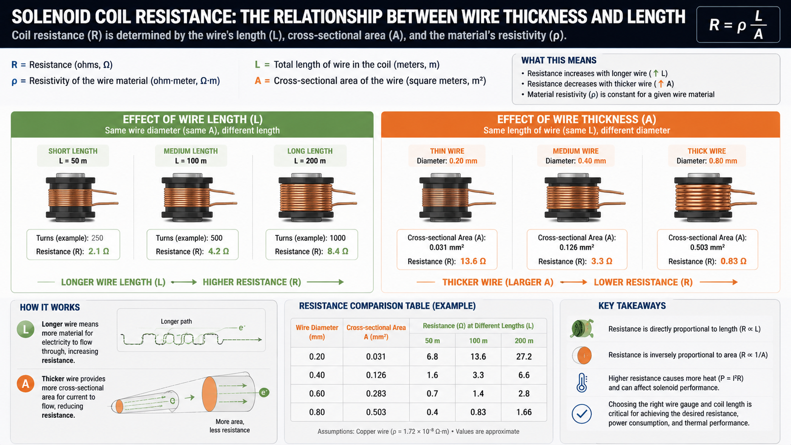
Think of building a coil like following a recipe. The main ingredients are the copper wire's thickness (gauge) and its length (number of turns). These two factors determine the final resistance value. It's not about aiming for a generic "high" or "low" number; it’s about creating the right combination for a specific task.
It's All About the Wire
The physics are straightforward. A longer, thinner wire creates more resistance, while a shorter, thicker wire creates less.2 As a designer, I use this relationship to control the coil's performance. When a purchasing manager asks for the "best" resistance, I usually steer the conversation toward the application itself. Are we building a coffee machine that needs a quick, powerful pulse, or a water control valve that needs to stay on for hours without getting too hot?
Balancing Power and Heat
This brings us to the most critical trade-off in coil design: power versus heat. A lower resistance allows more current to flow3, which generates a stronger magnetic force4. That sounds great, but it also produces more heat5. A higher resistance limits the current, resulting in less force but also less heat. The goal is to find the perfect balance.
| Resistance Level | Current Flow | Magnetic Force | Heat Generation | Best Use Case Example |
|---|---|---|---|---|
| Low | High | Strong | High | Short-burst actions, like a dispenser in a vending machine. |
| High | Low | Weaker | Low | Continuous-duty tasks, like a security door lock held open all day. |
Getting this balance right is what separates a reliable product from one that fails.
Why Does Coil Resistance Change When the Valve Gets Hot?
Have you ever noticed a component's performance changing as it heats up during use? This inconsistency can frustrate customers and lead to negative reviews for your appliance.
The resistance of a copper wire coil naturally increases as it gets hotter.6 This is a fundamental physical property of copper, not a defect. As the resistance rises, the current flowing through the coil decreases slightly7, which in turn reduces the magnetic force it produces.
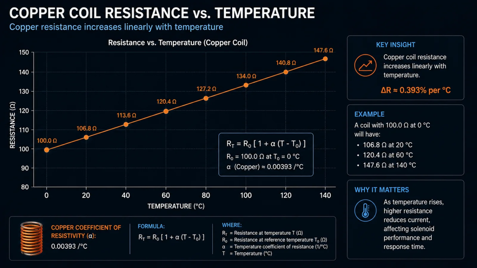
When a customer calls us worried that a coil's resistance reading changed after running for a while, I always reassure them that this is completely normal. In fact, we count on it. A key part of our design process is calculating the performance at the final operating temperature, not just its "cold" state when it's sitting on a shelf. This is why it's so helpful when our clients tell us exactly how their product will be used.
A Predictable Change
We don't see this temperature effect as a problem; we see it as a predictable variable that we engineer around. When we know a coil will be energized continuously in a hot environment, like inside a commercial dishwasher, we design it to have sufficient magnetic force even after its resistance has increased. We build in a performance margin to ensure it works reliably under the toughest conditions it will face in the real world. This is what we call designing for the "hot" state.
What This Means for Your Product
This is where the partnership between a buyer and a supplier becomes so valuable. If a coil is designed with only just enough force to work when it's cold, it might fail once it heats up. For example, a water inlet valve might open correctly the first time but then fail to stay open after 10 minutes of operation. This leads to an unreliable appliance and unhappy customers. By understanding the full operational context—the duty cycle, the ambient temperature, the required force—we can engineer a coil that performs consistently from the moment it's turned on until it's turned off.
Is Your Reading Normal? What Do Open or Short Circuit Ohms Mean?
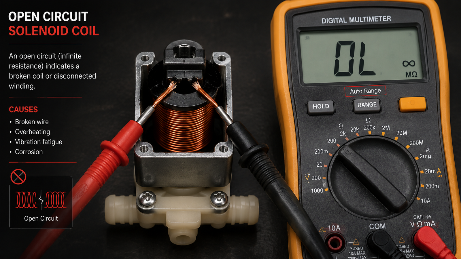
You've measured a coil's resistance with a multimeter, and the number is completely wrong. An extreme reading like this often signals a total failure that can shut down your appliance.
A multimeter reading of "open" or infinite resistance means the copper wire inside the coil is broken, so no electricity can flow. A reading near zero ohms indicates a "short circuit," where the wire's insulation has failed and current is taking a shortcut. Both readings mean the coil has failed.

When we get a field return, one of the first things my quality team does is measure the resistance. This simple test tells us a lot about what went wrong. It's a quick and effective diagnostic tool that helps distinguish between a true component failure and other issues in the appliance. These clear failure modes are very different from the slight resistance changes caused by temperature.
Diagnosing a Dead Coil
Understanding these readings can help your own quality teams quickly identify a faulty component. It's a straightforward process that requires only a basic multimeter. Here is a simple guide to what the different readings tell you.
| Multimeter Reading | Interpretation | Consequence for the Appliance |
|---|---|---|
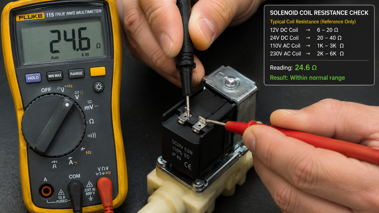
| Normal Value | The reading matches the manufacturer's spec (± a small tolerance). | The coil is electrically sound and should function correctly. |
| Infinite Resistance (Open Circuit) | The wire inside is physically broken or disconnected. | The solenoid will do nothing; it is completely dead. |
| Near-Zero Resistance (Short Circuit) | The wire's insulation has failed, causing loops to touch. | Creates a huge current spike, which can blow a fuse or damage the power supply8. The coil gets very hot, very fast. |
An open circuit might happen due to extreme vibration, while a short circuit is often the result of prolonged overheating that melts the wire's enamel coating. Both are permanent failures. Knowing this helps you separate a defective part from one that was simply misapplied.
How Do Designers Choose the Right Resistance for Different Voltages?
You source appliances for different global markets, like North America and Europe. Using a coil designed for the wrong voltage will cause immediate failure or very poor performance.
We choose a coil's resistance specifically to manage the current from a given voltage. To achieve the same power and force, a coil for a high-voltage system (like 230V in Europe) must have a much higher resistance than one for a low-voltage system (like 120V in the US).
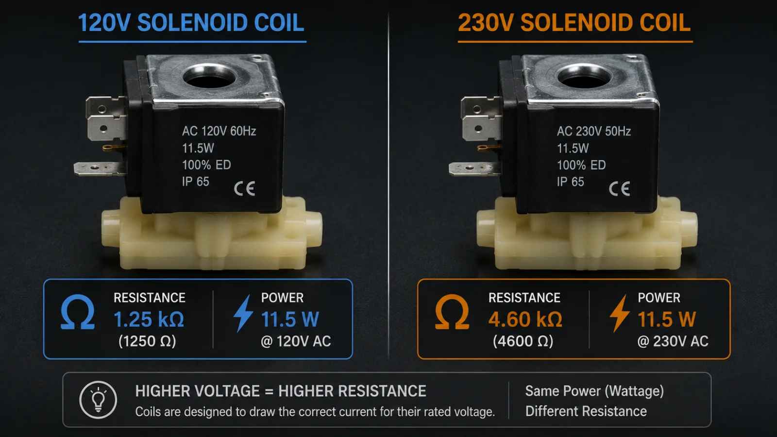
This is one of the most frequent topics I discuss with brand managers who are developing a global product line. They want one appliance that can be sold everywhere, but the electrical components inside must be tailored to each region. You can't just use the same solenoid coil for a 120V system and a 230V system. The coil itself has to be fundamentally different.
A Tale of Two Voltages
The relationship is all about achieving the right amount of power. We need a certain amount of power to generate the magnetic force required to open a valve or move a plunger. Since power is a product of voltage and current, if the voltage doubles, we have to cut the current in half to get the same power.9 The way we cut the current is by increasing the resistance. A coil designed for a 230V appliance will have roughly four times the resistance of a coil designed for an equivalent 120V appliance.10 They might look identical from the outside, but their internal wire windings are completely different.
The Wrong Match Is a Big Problem
Using the wrong coil is not a minor issue; it results in immediate and obvious failure.
- 120V coil on a 230V system: The high voltage will push way too much current through the low-resistance coil. It will overheat almost instantly, melting the insulation and causing a short circuit. We call this "letting the smoke out."
- 230V coil on a 120V system: The low voltage won't be able to push enough current through the high-resistance coil. This results in a very weak magnetic field, and the solenoid will likely fail to actuate at all. The valve won't open, or the lock won't retract.
This is why we always confirm the operating voltage. It's the first and most important question, as it dictates the entire design of the coil.
Conclusion
Solenoid coil resistance isn't a simple quality score; it's a specific design choice. By focusing on your application's needs—voltage, duty cycle, and force—you'll ensure you source the right component.
"Electrical resistivity and conductivity - Wikipedia", https://en.wikipedia.org/wiki/Electrical_resistivity_and_conductivity. For a uniform conductor, resistance is given by R = ρL/A, increasing with length L and decreasing with cross-sectional area A, directly linking resistance to wire length and thickness. Evidence role: mechanism; source type: encyclopedia. Supports: That a wire’s resistance depends on its length and cross-sectional area (thickness), per R = ρL/A.. ↩
"Electrical Wire Gauges - HyperPhysics", http://hyperphysics.phy-astr.gsu.edu/hbase/Tables/wirega.html. The resistivity relation R = ρL/A shows resistance grows with length and decreases with cross-sectional area, so thinner (smaller A), longer wire has higher resistance than thicker, shorter wire. Evidence role: mechanism; source type: education. Supports: That increasing length and reducing cross-sectional area of a wire increases its resistance per R = ρL/A.. ↩
"Ohm's law | Physics, Electric Current, Voltage | Britannica", https://www.britannica.com/science/Ohms-law. Ohm’s law states I = V/R for a given voltage V, so decreasing resistance R allows a larger current I to flow. Evidence role: mechanism; source type: encyclopedia. Supports: Ohm’s law showing current varies inversely with resistance for a given voltage.. ↩
"Solenoids as Magnetic Field Sources", http://hyperphysics.phy-astr.gsu.edu/hbase/magnetic/solenoid.html. The magnetic field of a solenoid (electromagnet) is proportional to current and turns (B ∝ nI), so increasing current strengthens the magnetic field and typically increases actuator pull before saturation. Evidence role: mechanism; source type: encyclopedia. Supports: That a solenoid/electromagnet’s magnetic field increases with current, which in turn increases magnetic pull in typical designs below saturation.. Scope note: Exact force depends on geometry, air gap, and magnetic saturation; the source establishes current–field proportionality rather than a specific force curve. ↩
"Joule heating - Wikipedia", https://en.wikipedia.org/wiki/Joule_heating. Resistive (Joule) heating follows P = I^2R, so greater current yields greater heat generation in the coil windings. Evidence role: mechanism; source type: encyclopedia. Supports: That resistive heating power scales with the square of current in a conductor.. ↩
"Temperature coefficient - Wikipedia", https://en.wikipedia.org/wiki/Temperature_coefficient. For metals like copper, resistance rises approximately linearly with temperature near room temperature, expressed as R(T) ≈ R0[1 + α(T − T0)] with positive α. Evidence role: mechanism; source type: encyclopedia. Supports: That copper exhibits a positive temperature coefficient of resistance with approximately linear behavior near room temperature.. ↩
"Ohm's law - Wikipedia", https://en.wikipedia.org/wiki/Ohm%27s_law. By Ohm’s law I = V/R, if the supply voltage is constant and the coil’s resistance increases with temperature, the current correspondingly decreases. Evidence role: mechanism; source type: encyclopedia. Supports: That at constant applied voltage, an increase in resistance results in lower current.. Scope note: The magnitude of the decrease depends on supply regulation and the coil’s temperature coefficient. ↩
"Circuit breaker - Wikipedia", https://en.wikipedia.org/wiki/Circuit_breaker. Fuses are overcurrent protection devices intended to open the circuit when fault currents (e.g., from short circuits) exceed their rated value, thereby protecting equipment from damage. Evidence role: mechanism; source type: encyclopedia. Supports: That fuses are designed to interrupt excessive currents from faults like short circuits to protect equipment.. Scope note: Whether a fuse opens or damage occurs depends on the circuit’s protection design and ratings. ↩
"Electric power - Wikipedia", https://en.wikipedia.org/wiki/Electric_power. Electrical power satisfies P = VI, so holding power constant when voltage doubles requires current to be reduced by half. Evidence role: mechanism; source type: encyclopedia. Supports: That electrical power equals voltage times current (P = VI), implying the stated trade-off.. ↩
"Ohm's law - Wikipedia", https://en.wikipedia.org/wiki/Ohm%27s_law. For a resistive coil at a given target power, P = V^2/R implies R ∝ V^2; thus a coil for a higher supply voltage requires much higher resistance, approximately scaling with the square of the voltage ratio. Evidence role: mechanism; source type: encyclopedia. Supports: That for a resistive load at a target power, R scales with V^2 (P = V^2/R), implying significantly higher resistance at higher voltage.. Scope note: Using 230 V vs 120 V, the ideal resistance ratio is (230/120)^2 ≈ 3.7; ‘roughly four times’ is an approximation and actual designs may deviate due to inductance, duty-cycle, and safety margins. ↩