Your machines are down, and the solenoid coil is the prime suspect. This costs you money and hurts your brand. I will show you how to find the real problem.
A burnt-out solenoid coil1 is rarely a quality defect. It's usually a mismatch between the coil's design and its actual use, especially with heat buildup. The best troubleshooting starts by understanding the coil's working environment, not just the coil itself.
For over 20 years in my factory, I’ve seen countless "faulty" coils sent back to us. But the real story is almost always more interesting than a simple defect. The coil is often just the messenger, telling you that something else in the system is wrong. When a coil burns out, it’s easy to blame the component. But replacing it without finding the root cause is like painting over rust. The problem will just come back. Let's dig into how you can become an expert at finding the real issue, saving you time, money, and headaches. We'll start by looking at the warning signs you can spot before you even pick up a tool.
Why does a Solenoid Coil Fail: Recognizing the Signs before Testing?
A coil suddenly stops working, and your machine halts. You are left guessing the cause. Wasting time trying to figure it out means lost production and frustrated customers.
Common signs of failure include visible burn marks, a melted or deformed plastic bobbin2, and a distinct burnt smell. These almost always point to overheating, which is the number one killer of solenoid coils. Recognizing these signs immediately tells you where to look for the problem.
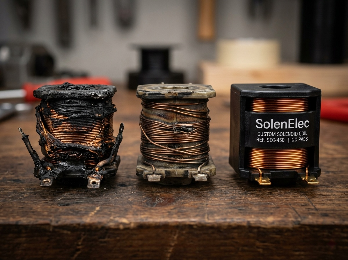
Before you begin any electrical testing, a simple visual inspection can tell you a lot. In my experience, most coil failures are not sudden events. They are the result of a slow death caused by conditions that were not part of the original design.
The Slow Cooker Effect: Overheating
The most common issue I see is what I call the "slow cooker effect3." Heat builds up inside the coil faster than it can escape. This happens when a coil is energized for too long, the voltage is too high, or it is in a hot, poorly ventilated space. The first thing to fail is the thin enamel insulation4 on the copper wire. Once that insulation breaks down, the wires touch, creating a short circuit. That’s when the coil finally burns out. It didn't "go bad"; it was slowly cooked.
Beyond Heat: Other Failure Points
While heat is the main villain, other issues can also cause failure. It is important to know what they look like.
| Visual Sign | Likely Cause | What It Means for Your System |
|---|---|---|
| Burnt Smell / Discoloration | Overheating | The coil's duty cycle5 or environment is wrong. |
| Cracked or Melted Bobbin | Severe Overheating | A major system fault, like incorrect voltage, is present. |
| No Visible Damage | Electrical Open/Short | The internal wire broke from vibration or a manufacturing issue. |
| Physical Dents or Scratches | Mechanical Impact | The coil was damaged during installation or by machine vibration. |
Looking for these signs first helps you understand if the problem is heat, electrical, or mechanical. This simple step can save you hours of unnecessary testing.
How do you Test Solenoid Coil Continuity and Resistance with a Multimeter?
You have a suspect coil, but you're not sure if it's truly dead. Throwing it away is wasteful. Without a simple test, you could be replacing perfectly good parts.
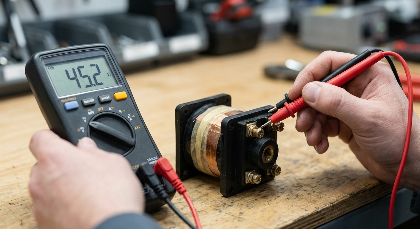
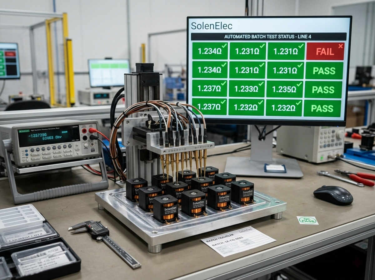
Set your multimeter to the resistance (Ω) setting6 and disconnect the coil from power. A healthy coil shows a specific resistance value7. A reading of "OL" or infinite means a broken wire (open circuit). A reading near zero ohms means a short circuit.
This is the most basic electrical check, and it gives you a clear yes or no answer about the coil's internal wiring. You don't need to be an electrical engineer to do this. Just remember to always disconnect the coil from any power source before you begin. Safety is the most important first step.
Step 1: The Continuity Check
Think of continuity as checking if a road is complete from one end to the other. You are making sure the copper wire inside the coil is an unbroken path. Most multimeters have a continuity setting that beeps if the path is complete. If you get a beep, the wire is not broken. If there is no beep, the coil is an "open circuit" and is definitely bad. It needs to be replaced.
Step 2: Measuring Resistance
If the continuity test passes, the next step is to measure resistance. This tells you not just if the road is complete, but if it is the right road. Every coil is designed to have a specific resistance value7, measured in ohms (Ω). This value depends on the length and thickness of the wire.
| Multimeter Reading | Interpretation | Coil Status |
|---|---|---|
| Specific Ω Value (e.g., 50 Ω) | Correct Resistance | Likely Good. The electrical path is intact. |
| "OL" / Infinite (∞) | Open Circuit | Bad. The wire is broken inside. |
| Near 0 Ω | Short Circuit | Bad. The wires are touching, creating a shortcut. |
You need to know the correct resistance value7 for your coil, which should be in its technical datasheet. If the reading is very different from the specification, the coil is damaged, even if it looked fine visually.
What is the Magnetic Pull Test: A Quick Way to Check Solenoid Activation Field?
Your multimeter test shows the coil is electrically fine, but the solenoid valve still won't move. You are left wondering if the coil is too weak or if the problem is mechanical.
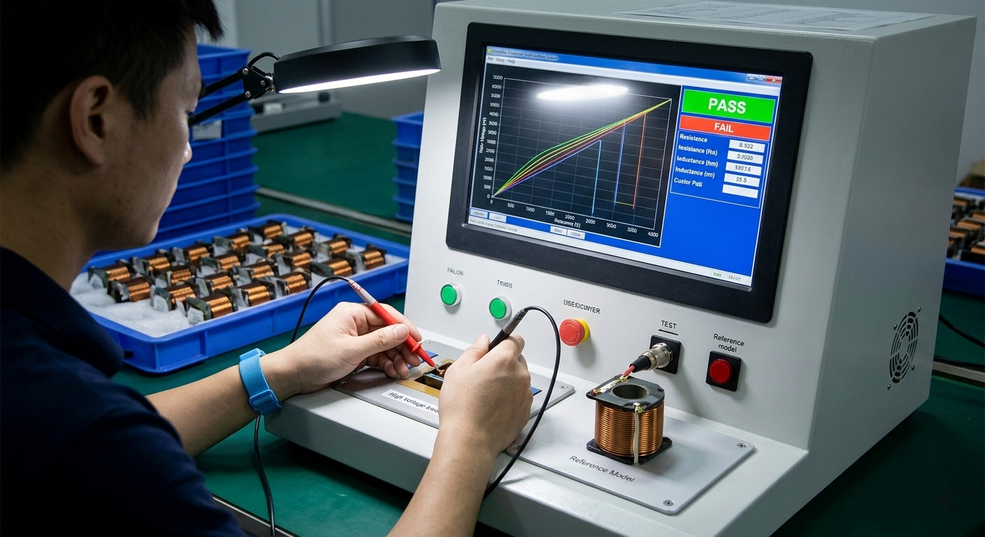
With the coil safely powered on, bring a small piece of ferrous metal, like a screwdriver tip, near its center. A healthy coil will create a noticeable magnetic pull. No pull means it is not generating a magnetic field, even if its resistance is normal.
This is a great functional test. It moves beyond theory and checks if the coil is actually doing its job, which is to turn electricity into a magnetic force. A coil can have the correct resistance but still fail to generate a strong enough field if there are very subtle shorts or if the voltage supply is too low.
How to Perform the Test Safely
Safety is critical here because the coil must be energized. This test should only be performed on low-voltage systems unless you are a qualified technician. Make sure the coil is securely mounted and cannot move. Apply the correct voltage to the coil's terminals. Then, slowly bring a small metal object, like the shaft of a screwdriver, towards the hole in the center of the coil. Do not touch the electrical terminals. You should feel a distinct pull as the object gets close.
Interpreting the Results: Strong, Weak, or No Pull
The feeling of the pull gives you immediate feedback.
- Strong Pull: The coil is generating a healthy magnetic field. It is doing its job. If the solenoid is still not working, the problem is almost certainly mechanical. Look for a stuck plunger, debris in the valve, or incorrect pressure.
- Weak Pull: The coil is working, but not at full strength. This could mean the supply voltage is too low, or there are minor short circuits inside the coil that the resistance test did not catch.
- No Pull: If the coil has voltage but generates no magnetic field, it is faulty. Even if it passed the resistance test, something is preventing it from working correctly. It needs to be replaced.
This simple, practical test helps you quickly decide if your focus should be on the electrical coil or the mechanical parts of the assembly.
What are Advanced Factory-Level Diagnostics if the Basics Pass but Failure Persists?
Your basic tests all pass, but coils continue to fail in the field. Your team is frustrated. You start to blame the supplier, but you suspect the problem is more complex.
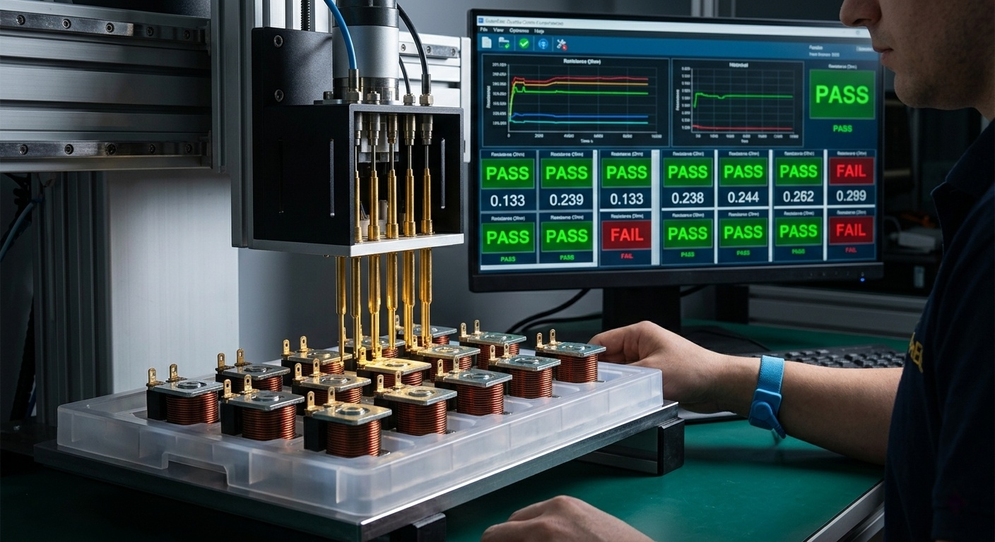
We bring the customer's entire assembly into our lab. We run it under real-world conditions, using thermal cameras8 and life-cycle testers9 to find the hidden problem. The issue is almost always how the coil is used, not how it was made.
When a customer has repeated failures, the answer is never found by testing the coil alone. We have to test the coil in its system. This is where my 20+ years of experience really comes into play. The lab data tells a story that a multimeter never could.
A Case Study: The Overheating Water Valve
Let me tell you a story. A major European client who makes water valves kept having our coils burn out. They were convinced we had a quality problem. Their engineers tested the coils, and the resistance was perfect. They sent a batch back to us, and we tested them. Again, all specifications were normal.
So, we asked for their valve assembly. We mounted our coil on it and ran it at the voltage and duty cycle5 they used in the field. Using a thermal camera, we saw the problem in minutes. The coil temperature just kept climbing, far past its rated limit. It turned out they designed the valve for continuous, 24/7 operation but had selected a coil designed for intermittent use. The coil was trapped in a tight space with no airflow. It was slowly cooking itself to death. The coil wasn't faulty; the application was wrong.
The Real-World Application Test
This is our most powerful diagnostic tool. We don't just test the coil; we test the system.
- Heat Rise Test: We measure the coil's temperature over time in its actual housing to see if it stabilizes at a safe level.
- Life Cycle Testing: We simulate months or years of use in just a few days, turning the coil on and off thousands of times to find the true point of failure.
These tests show us exactly how the coil behaves in the real world. This is how we find the root cause and provide a solution that actually works.
How do you Select and Maintain Coils: Expertise Insights to Stop Burnout Before It Starts?
You're tired of troubleshooting failures. You want to prevent them from happening in the first place. But choosing the wrong coil leads to predictable failures that cost you money and reputation.
The secret is to match the coil to its exact application. Stop asking for a "stronger" coil and start defining the working environment: duty cycle5, temperature, and airflow. A perfectly matched coil is the most reliable coil.

The solution to the European client's problem was not to just make the coil "better." A bigger, more powerful coil would have likely produced even more heat and failed faster. Instead, we redesigned the coil to fit the application.
It's Not About Strength, It's About Fit
Here is what we did for that water valve client:
- Adjusted the Winding: We wound the copper wire slightly looser. This created tiny air gaps that helped heat escape from the inside.
- Upgraded Materials: We switched to a copper wire with a higher temperature-rated enamel insulation.
- Modified the Structure: We changed the plastic injection-molded bobbin to include small vents, creating a path for heat to exit.
The result? The magnetic force was slightly lower, but the coil's operating temperature dropped dramatically. Its lifespan increased by several times, and the client never had a burnout problem again. The best coil is not the strongest one. It is the one that is designed for its environment.
Key Questions for Your Coil Supplier
When you order coils, don't just provide a resistance value7. Give your supplier the full picture.
| Application Factor | Key Design Consideration | Why It Matters to Prevent Burnout |
|---|---|---|
| Duty Cycle | Intermittent (short bursts) vs. Continuous (always on) | A continuous-duty coil must be able to get rid of heat constantly. |
| Ambient Temperature | The temperature of the air around the coil. | A hot environment reduces the coil's ability to cool itself. |
| Enclosure & Airflow | Is the coil in a sealed box or open to the air? | No airflow traps heat, requiring a special thermal design. |
| Voltage Supply | Is the voltage perfectly stable or does it fluctuate? | Voltage spikes cause current surges and rapid overheating. |
Working with a supplier who asks these questions is the first step to eliminating coil failure forever.
Conclusion
Coil failure is usually a system problem, not a component problem. Match the coil design to its real-world use and work with your supplier to ensure long-term reliability.
Understanding the causes of solenoid coil burnout can help prevent future failures and save costs. ↩
Knowing the causes of bobbin deformation can guide corrective actions to prevent coil failure. ↩
Understanding the slow cooker effect can help in designing systems that prevent coil overheating. ↩
Learning about insulation issues can lead to better coil design and longer lifespan. ↩
Understanding duty cycle requirements ensures the coil is suitable for its application, preventing failures. ↩
Knowing how to test coil resistance can confirm coil health and prevent wasteful replacements. ↩
Understanding resistance value helps ensure your solenoid coil is functioning correctly, preventing unnecessary replacements and saving costs. ↩
Thermal imaging can reveal hidden overheating problems, leading to effective solutions. ↩
Life-cycle testing simulates real-world conditions, identifying long-term coil issues. ↩