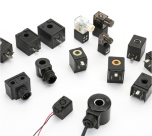
How to Choose the Right Solenoid Coil for Pneumatic Valves?
Choosing the wrong solenoid coil leads to failures and costly downtime. You need a reliable component, but the options are overwhelming. This guide simplifies the process for your specific application.
The best way to choose a solenoid coil for a pneumatic valve is to treat it as a risk management process. Instead of looking for a single "best" coil, you must match the coil's electrical, mechanical, and material properties to your specific operational environment and performance requirements.
After more than 20 years in this industry, I've seen countless procurement managers struggle with this choice. They focus on the unit price, but the real cost of a coil isn't its purchase price. It's the cost of failure: production stops, warranty claims, and damage to your brand's reputation. The key is to shift your thinking from "Which coil is cheapest?" to "Which coil presents the lowest long-term risk for my application?" Let's break down the critical questions you need to ask.
What Is the Difference Between AC and DC Solenoid Coils for Pneumatic Systems?
You need quick valve actuation, but you're worried about energy use and heat. Choosing between AC and DC power feels like a technical puzzle with big consequences for your system's performance.
AC (Alternating Current) coils offer a strong initial pull-in force for faster valve actuation.1 DC (Direct Current) coils provide smoother, quieter operation with lower power consumption and less heat, making them ideal for continuous-duty applications.
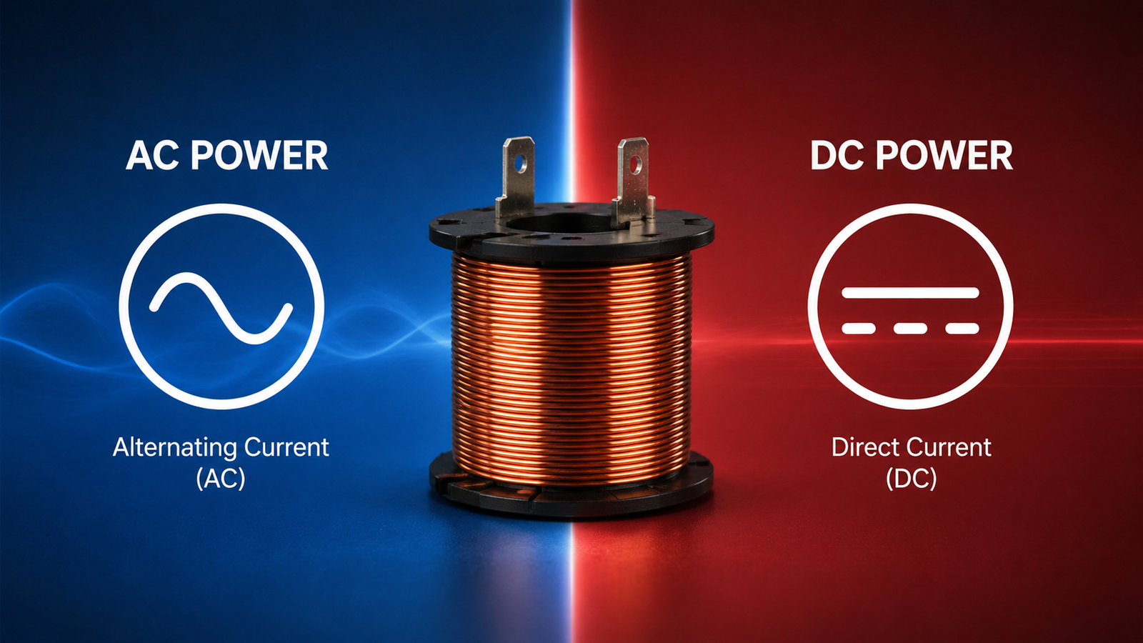
In my experience, this choice comes down to a trade-off between speed and efficiency. A common question I get from clients is which one is "better," but the answer always depends on the job. AC coils are great for applications that need a fast, powerful response. However, they have a high inrush current2 and can hum or vibrate. If an AC-powered valve gets stuck and can't fully close, the coil will quickly overheat and fail.3 On the other hand, DC coils are the workhorses for control systems. They run cooler and are more energy-efficient, which is a major advantage for systems that are always on. They don't have the high inrush current of AC coils, leading to a longer, more reliable service life. When a customer needs reliability over raw speed, I almost always point them toward a DC solution.
| Feature | AC Solenoid Coil | DC Solenoid Coil |
|---|---|---|
| Actuation Speed | Faster, high initial force | Slower, consistent force |
| Power Consumption | Higher, especially at inrush | Lower, more efficient |
| Heat Generation | Higher, risk of burnout if stalled | Lower, better for continuous use |
| Operation | Can hum or vibrate | Quiet and smooth |
| Best For | Rapid cycling applications | Continuous duty, control systems |
How Do You Match Solenoid Coil Voltage and Power Ratings to Your Pneumatic Valve?
A voltage mismatch seems like a small error, but it can destroy your equipment. You need to ensure the coil you choose works perfectly with your power supply, or you risk immediate failure.
Matching voltage and power is critical. The coil's voltage must match your system's power supply exactly.4 The power rating (in watts) determines the magnetic force, so it must be sufficient to actuate the valve without causing overheating.
I've seen too many warranty claims that trace back to a simple voltage mismatch. It's a fundamental but often overlooked detail. If you supply a 24VDC coil with only 20V, the magnetic field will be too weak.5 The valve might not open at all, or it might actuate slowly and unreliably, leading to process errors. On the other side of the coin, if you connect that same 24VDC coil to a 30V supply, you'll get a very strong pull. But that extra voltage will cause the coil to draw too much current, leading to rapid overheating and a drastically shortened life. The coil will burn out. We always advise our clients to verify their power supply's stability. Power ratings are just as important. A higher wattage means more force but also more heat.6 You must choose a coil powerful enough to overcome the valve's spring and pressure, but not so overpowered that it wastes energy and creates a thermal management problem.
Continuous vs. Intermittent Duty Cycle: Which Solenoid Coil Fits Your Application?
You've found a coil that meets your specs, but will it last? Using a coil with the wrong duty cycle rating is a common cause of premature failure, leading to unexpected downtime and maintenance costs.
Choose a continuous-duty coil if it will be energized for more than a few minutes at a time.7 Use an intermittent-duty coil only for applications with short "on" times and long "off" times to allow for cooling.
This is one of the most important decisions, and it directly impacts long-term reliability. A coil's duty cycle rating tells you how long it can be energized without overheating. A continuous-duty coil is designed to be left on 100% of the time. It's built to dissipate the heat it generates constantly. An intermittent-duty coil is not. It's designed for short bursts of power, like in a door lock or a single-shot pneumatic punch. I once worked with a client whose assembly line kept failing. It turned out they had used intermittent-duty coils on a continuously operating sorting machine to save a few dollars per unit. The coils were burning out every few weeks. The cost of downtime and replacement far exceeded the initial savings. We switched them to a continuous-duty coil, and the problem disappeared. Always ask your supplier: "Is this coil rated for 100% continuous duty?"
| Duty Cycle | Description | Common Application |
|---|---|---|
| Continuous Duty | Can be energized 100% of the time without overheating. | Process control valves, sorting gates. |
| Intermittent Duty | Requires an "off" period to cool down after activation. | Door latches, tool changers, short-cycle actuators. |
What Insulation Class and IP Rating Do You Need for Harsh Pneumatic Environments?
Your equipment operates in a tough environment with heat, dust, and moisture. Choosing a standard coil is risky, as a failure due to environmental factors can bring your entire operation to a halt.
The insulation class (e.g., Class F, Class H) must exceed your maximum operating temperature. The IP (Ingress Protection) rating must be high enough to protect against dust and water specific to your environment (e.g., IP65, IP67).
Context is king here. A spec sheet from a clean lab means nothing if your valve is mounted next to a hot engine or in a wash-down area. The coil's insulation class tells you the maximum temperature the coil wire's enamel can withstand before it breaks down. For example, Class F is rated for 155°C, while Class H is rated for 180°C.8 I always tell procurement managers to consider the worst-case ambient temperature and add the heat generated by the coil itself. Choosing a higher class provides a safety margin and extends the coil's life. The IP rating is just as critical. It tells you how well the coil is sealed against solids (like dust) and liquids. A rating of IP65 means it's dust-tight and protected against water jets. IP67 means it can be temporarily submerged.9 We’ve seen failures caused by specifying an IP54 coil for an outdoor application; the first rainstorm caused a short circuit. Matching these ratings to your real-world conditions is non-negotiable for reliability.
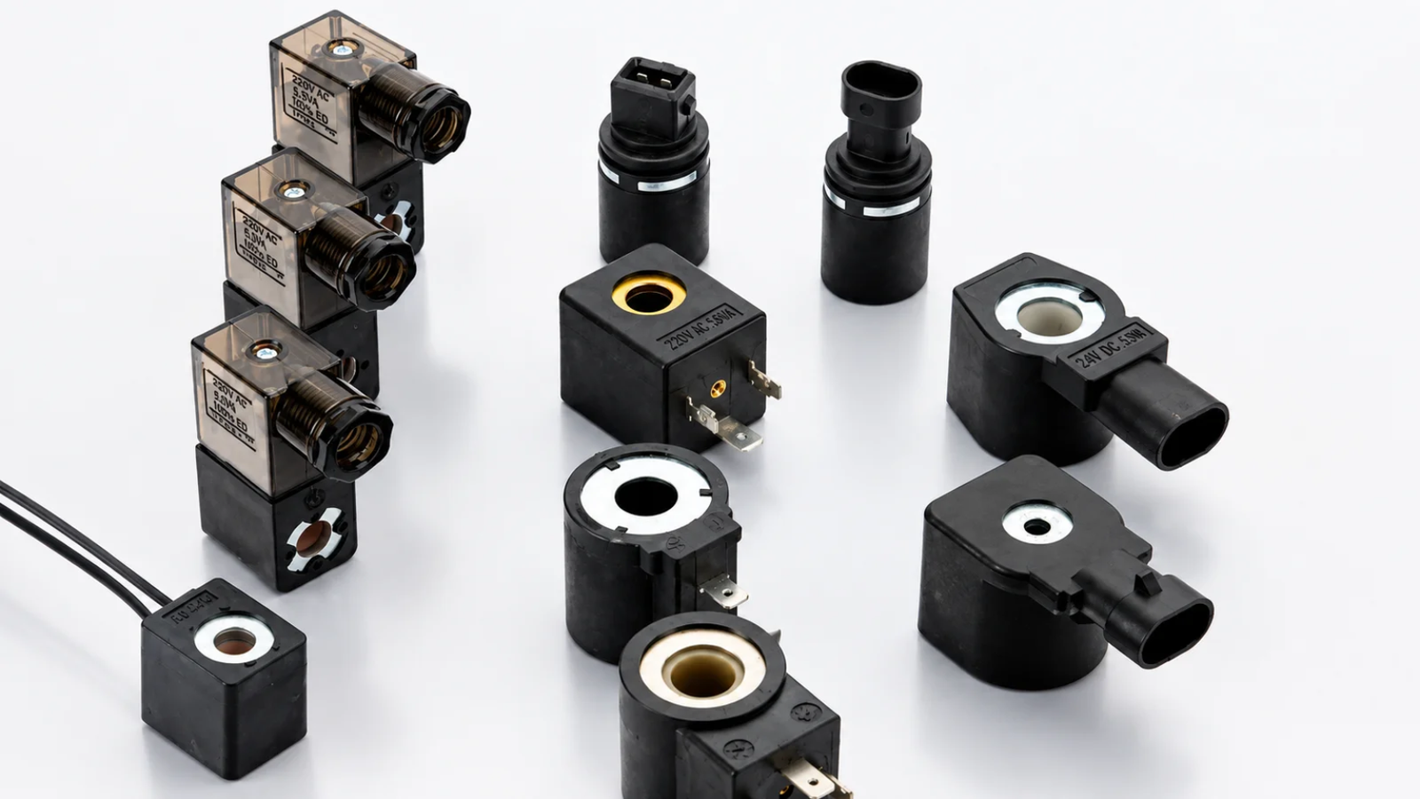
How Do You Choose Between DIN Connector, Flying Leads, or Deutsch Connections?
You've specified the coil's performance, but how will it connect to your system? The choice of connection type impacts installation time, maintenance ease, and reliability in the field, affecting your total cost.
DIN connectors are ideal for standard industrial use, offering quick installation and replacement. Flying leads provide flexibility for custom wiring, while robust Deutsch connectors are best for harsh environments with high vibration and moisture.
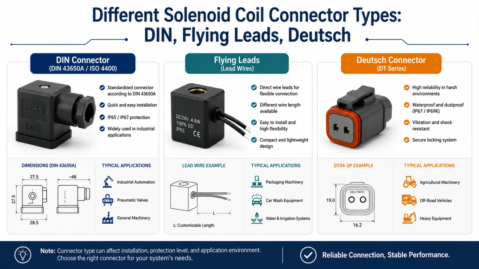
This decision often comes down to balancing manufacturing efficiency with field serviceability. The DIN 43650 connector is a workhorse in industrial automation. It's standardized, easy to connect and disconnect, and offers decent protection (often IP65) when properly installed with a gasket. It's perfect for factory floors and control cabinets. Flying leads are simply wires coming out of the coil. They offer the most flexibility for routing and connecting within tight spaces, but they require more labor to terminate and seal properly. If not done right, they are a common point of failure. When customers operate mobile equipment or systems with heavy vibration and exposure to the elements, I guide them toward Deutsch-style connectors. These are sealed, locking connectors designed for the automotive and heavy-equipment industries.10 They cost more upfront, but they prevent connection failures that could disable a valuable piece of machinery in the field.
Conclusion
Choosing the right solenoid coil is a process of managing risk by matching the coil's characteristics to your specific application. Prioritize reliability over unit cost to ensure long-term performance and brand reputation.
"Solenoid valve - Wikipedia", https://en.wikipedia.org/wiki/Solenoid_valve. Electrical engineering training materials explain that AC-driven solenoids experience high inrush current when the armature is unseated, generating a strong initial magnetic force that promotes rapid pull-in; as the armature seats, inductance increases and current falls, which distinguishes AC actuation characteristics from DC. Limitation: The exact actuation speed and force depend on the specific coil design, valve geometry, and system load. Evidence role: mechanism; source type: education. Supports: That AC solenoids develop high initial force due to inrush current when the armature is unseated, aiding faster pull-in compared with steady DC operation.. ↩
"Inrush current - Wikipedia", https://en.wikipedia.org/wiki/Inrush_current. Instructional resources on solenoids describe that, under AC excitation, the coil exhibits low reactance with an open magnetic circuit so current is initially high; seating of the armature increases inductance and raises reactance, reducing coil current. Limitation: Quantitative inrush magnitude varies with coil winding, core material, and mechanical gap. Evidence role: mechanism; source type: education. Supports: That AC solenoids draw higher current at energization before the armature closes, due to low inductive reactance, and current decreases as inductance rises when the armature seats.. ↩
"Solenoid overheating", https://forum.allaboutcircuits.com/threads/solenoid-overheating.203238/. Technical training sources explain that AC solenoid current depends on armature position; with the armature unseated, inductance remains low and current stays elevated, increasing I^2R heating and the risk of thermal failure if the condition persists. Limitation: Actual time-to-failure depends on duty rating, thermal path, and ambient conditions. Evidence role: mechanism; source type: education. Supports: That in AC solenoids the armature position strongly affects inductance and current; a failure to seat leaves low inductance and high current, increasing heat and risk of thermal damage.. ↩
"Electromagnetism - Wikipedia", https://en.wikipedia.org/wiki/Electromagnetism. Basic electromagnetism and circuit principles support matching coils to their rated voltage: undervoltage reduces current and magnetic force, risking failure to actuate, while overvoltage increases current and I^2R heating, risking thermal damage. Limitation: Many coils allow a specified tolerance around the nominal voltage; exact acceptable ranges are product-specific. Evidence role: general_support; source type: education. Supports: That using a supply significantly below or above a coil’s rated voltage reduces magnetic force or increases heating, respectively.. ↩
"Magnetic field - Wikipedia", https://en.wikipedia.org/wiki/Magnetic_field. Reference materials on electromagnets state that magnetic force is determined by ampere-turns, so reducing the applied DC voltage reduces current and the resulting field, which can prevent a solenoid from developing sufficient force to actuate. Limitation: The precise voltage at which actuation fails depends on coil resistance, spring load, and fluid pressure. Evidence role: mechanism; source type: encyclopedia. Supports: That magnetic force in a solenoid depends on current (ampere-turns), which decreases with lower applied DC voltage given fixed resistance.. ↩
"Electromagnetism - Wikipedia", https://en.wikipedia.org/wiki/Electromagnetism. Encyclopedic treatments of electromagnets show that magnetic force increases with current (ampere-turns), whereas resistive losses scale with I^2R, so higher electrical power yields more force but also more heat to be managed. Limitation: Actual force and heating depend on geometry, materials, duty cycle, and cooling provisions. Evidence role: mechanism; source type: encyclopedia. Supports: That higher current (and thus higher electrical power) in a coil increases magnetic force, while resistive losses scale with I^2R and raise temperature.. ↩
"Thermal equilibrium - Wikipedia", https://en.wikipedia.org/wiki/Thermal_equilibrium. Standard duty classifications define continuous duty as operation long enough to reach thermal equilibrium, implying component selection that can dissipate heat during sustained energization. Limitation: Formal duty classifications (e.g., IEC motor duty types) are defined for motors and are applied by analogy to solenoids; the “few minutes” threshold is application-specific. Evidence role: definition; source type: encyclopedia. Supports: That continuous duty refers to operation long enough to reach thermal steady state and requires designs that can dissipate heat under sustained energization.. ↩
"Insulation system - Wikipedia", https://en.wikipedia.org/wiki/Insulation_system. Encyclopedic references on electrical insulation systems list thermal classes with their maximum temperature ratings, including Class F at 155°C and Class H at 180°C. Limitation: Manufacturers may specify allowable temperature rise and ambient assumptions that affect practical limits. Evidence role: definition; source type: encyclopedia. Supports: That internationally recognized insulation thermal classes designate Class F at 155°C and Class H at 180°C.. ↩
"IP code - Wikipedia", https://en.wikipedia.org/wiki/IP_code. IP Code references define IP65 as dust-tight with protection against water jets and IP67 as providing protection against temporary immersion under standardized test conditions. Limitation: Actual protection depends on correct installation and sealing per the product’s instructions. Evidence role: definition; source type: encyclopedia. Supports: That IP65 and IP67 have the specified dust and water ingress protections under the IP Code.. ↩
"SAE J1587 - Wikipedia", https://en.wikipedia.org/wiki/SAE_J1587. Connector references describe Deutsch series connectors as environmentally sealed, locking designs widely applied in automotive and heavy-duty equipment environments. Limitation: Specific series (DT, DTM, etc.) and sealing performance vary by model and installation. Evidence role: general_support; source type: encyclopedia. Supports: That Deutsch connectors are designed as environmentally sealed, locking connectors and widely used in automotive and heavy-equipment contexts.. ↩