Choosing the wrong solenoid can lead to product failure and high warranty costs.1 An incorrect choice means your device might fail, damaging your brand's reputation and leading to expensive recalls.
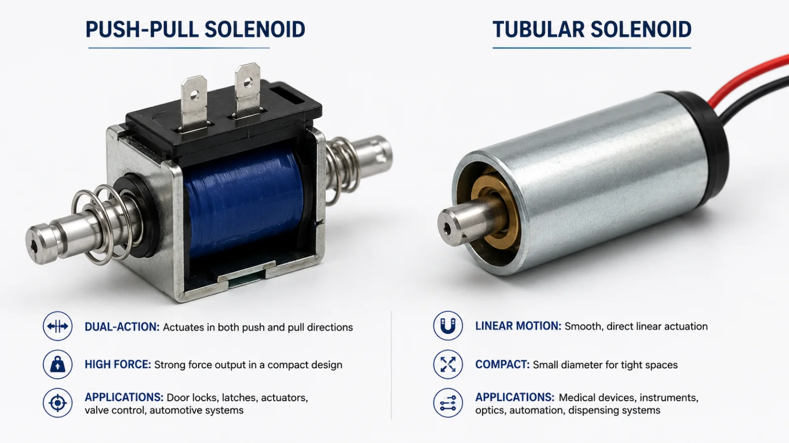
The best solenoid is the one that perfectly matches your application's specific needs for force, stroke length, lifespan, and noise level.2 Push-pull solenoids offer high force for short strokes, while tubular solenoids provide smoother, long-life operation for precision tasks. It's about matching the component to the job.
Picking the right component for a large-scale project can feel overwhelming. The technical specifications for solenoids often look similar on paper, but their real-world performance can be very different. This small difference can have a huge impact on your final product's reliability and your brand's reputation. That's why understanding the fundamental distinctions is so important. We're going to break down everything you need to know, so you can make your next decision with confidence and avoid costly mistakes down the line.
What Is the Difference Between Push-Pull and Tubular Solenoids? A Core Comparison?
You know you need a linear solenoid, but the technical jargon is confusing. This can lead to costly mistakes in your design and production when components don't perform as expected.
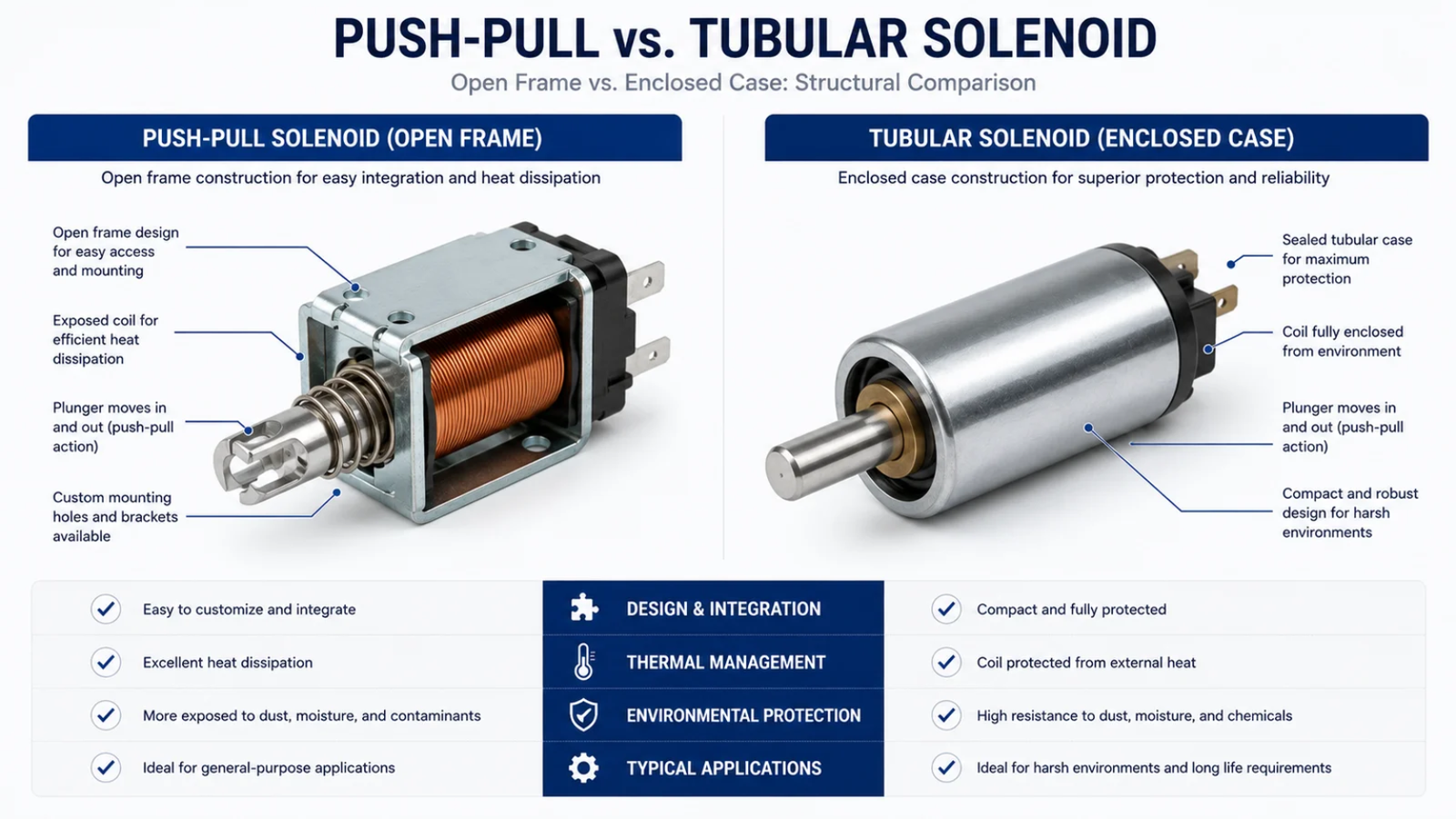
The main difference lies in their physical construction and resulting magnetic efficiency.3 Push-pull solenoids use an open C-frame or D-frame, which is cost-effective and provides strong initial force.%%%FOOTNOTE_REF4%%% [Tubular solenoids have a cylindrical, enclosed case, which contains the magnetic field for a smoother stroke and better protection.](https://en.wikipedia.org/wiki/Solenoid(engineering))5
Let's dive deeper into what these structural differences mean for performance. A push-pull solenoid's open frame is easier to manufacture, which often makes it a more economical choice. However, the magnetic field it generates is less contained. Some magnetic flux "leaks" into the surrounding air, making it slightly less efficient.6 This open design also means the internal plunger is more exposed to dust, moisture, and other environmental contaminants, which can affect its long-term reliability.7
A tubular solenoid, on the other hand, has a metal tube that encloses the coil and plunger. This tube does two things very well. First, it acts as a frame and guides the magnetic flux, concentrating the magnetic field and making the solenoid more efficient. This results in more force for its size and less wasted energy as heat. Second, the enclosure protects the internal mechanism from the outside world, significantly increasing its durability and lifespan, especially in demanding or dirty environments.
| Feature | Push-Pull Solenoid | Tubular Solenoid |
|---|---|---|
| Construction | Open C-frame or D-frame | Enclosed cylindrical tube |
| Magnetic Field | Less contained, some leakage | Highly contained and efficient |
| Stroke Profile | High initial force, then drops | Smoother, more consistent force |
| Environmental Seal | Exposed to elements | Protected from dust & debris |
| Common Use Case | Intermittent, high-force tasks | High-cycle, precision tasks |
How a Push-Pull Solenoid Works: Understanding Dual-Directional Stroke Efficiency?
Your application needs a fast, powerful, and cost-effective linear motion. But choosing the wrong mechanism can result in weak performance, failing to do the job when it matters most.
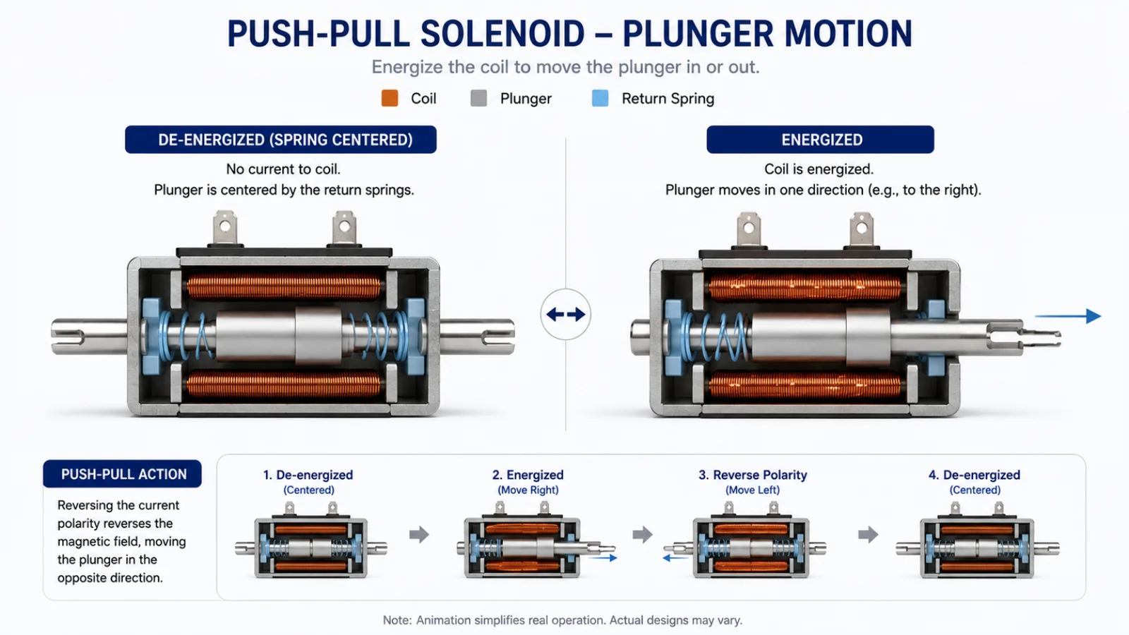
A push-pull solenoid uses an open-frame electromagnet to move a metal plunger. When you apply power, the coil creates a magnetic field that pulls the plunger in ("pull" type). Some designs have a rod attached that pushes outward, creating a "push" motion. They provide a strong, fast stroke.
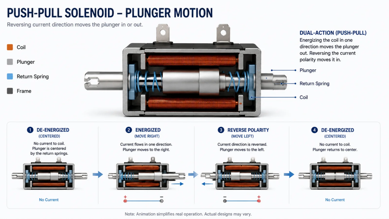
The mechanics are simple yet effective. The basic components are the frame (often shaped like a 'C' or 'D'), the copper wire coil, and the movable iron plunger. When electricity flows through the coil, it becomes a powerful electromagnet. The magnetic field attracts the iron plunger, pulling it toward the center of thecoil with great speed and force. This is the "pull" action, perfect for things like releasing a latch or opening a valve.
To get a "push" action, manufacturers typically attach a non-magnetic rod to the plunger that extends out the other side. As the plunger is pulled into the coil, the rod pushes outward. This dual-directional potential makes them very versatile. Their main advantages are a high force-to-size ratio, very fast reaction times8, and lower manufacturing costs due to the simpler open-frame design. However, this design can also be a drawback. The impact of the plunger can be noisy, and the less-efficient magnetic field can generate more heat, especially during continuous use. The quality of the frame and plunger guidance is critical to prevent wear and ensure a long service life.
The Advantages of Tubular Solenoids: Why Enclosed Designs Excel in Heavy-Duty Cycles?
You need a solenoid that lasts for millions of cycles without failing. Standard solenoids wear out, causing expensive downtime and repairs for your customers, which erodes trust in your brand.
Tubular solenoids excel in heavy-duty use because their enclosed design protects the plunger and coil from debris. This also creates a more efficient magnetic field, leading to smoother operation, lower wear, and a much longer operational life, perfect for high-precision applications that run continuously.
The key to a tubular solenoid's longevity is its design. The plunger travels inside a smooth, continuous metal tube. This tube acts as a built-in bearing surface, guiding the plunger precisely and reducing side-to-side movement and friction. Less friction means less wear on the plunger and the guide, which is why these solenoids can often achieve tens of millions of cycles.9 In an open-frame solenoid, the plunger might have more room to wobble, leading to faster wear.
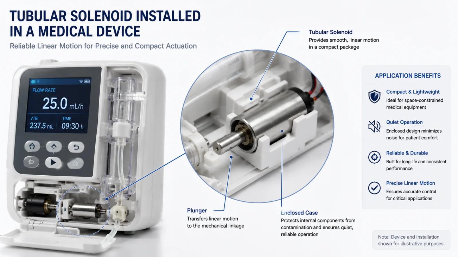
Furthermore, the enclosed design creates a superior magnetic circuit. The steel housing contains and directs the magnetic flux, focusing all its energy on moving the plunger. This efficiency means less electrical energy is wasted as heat, allowing the solenoid to run cooler and more consistently, even when activated for long periods.10 The smooth, guided travel and contained mechanism also result in significantly quieter operation compared to the distinct "snap" of a push-pull solenoid. This combination of durability, efficiency, and low noise makes them the ideal choice for medical analysis equipment, automotive controls, and premium smart home devices where failure is not an option.
Force-Stroke Curves: Comparing the Mechanical Output of Linear Solenoids?
Datasheets are filled with graphs that are hard to understand. If you misinterpret a force-stroke curve, you might choose a solenoid that is too weak at the critical point in its movement.
A force-stroke curve shows the force a solenoid exerts at different points of its travel.11 Push-pull solenoids typically have a high starting force that drops off quickly. Tubular solenoids offer a flatter curve, providing more consistent force throughout the stroke, which is better for controlled motion.
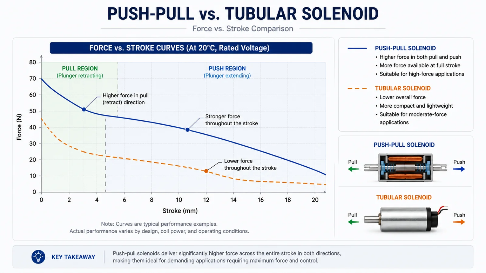
Let's break down how to read these critical graphs. The vertical axis (Y-axis) shows force, and the horizontal axis (X-axis) shows the plunger's position, or stroke. For a pull-type solenoid, the beginning of the stroke (furthest from the coil) is on the right, and the end of the stroke (fully seated in the coil) is on the left.
The curve for a typical push-pull solenoid looks like a steep hill. It has very high force at the beginning of its stroke but loses force rapidly as the plunger moves closer to its final position. This is perfect for tasks that require a strong initial "breakaway" force, like unlatching a heavy door lock. After that initial powerful pull, less force is needed to complete the motion.
In contrast, the curve for a tubular solenoid is much flatter. The force it exerts is more uniform from the beginning of the stroke to the end. It may not have the same high peak force as a push-pull model, but its consistent output is ideal for applications where you need smooth, controlled movement over the entire travel distance, such as in a precision valve or a medical pump. As a manufacturer with over 20 years of OEM experience, we can customize the coil winding and materials to shape these curves to fit your exact project requirements.
Selection Guide: How to Choose Between Push-Pull and Tubular Solenoids for OEM Projects?
You've reviewed the specs, but you're still unsure which solenoid is right. Making the wrong choice on a large OEM order can be a multi-million dollar mistake, and the pressure is immense.
For your OEM project, choose a push-pull solenoid for high-impact, short-stroke tasks like vending machine dispensers. Choose a tubular solenoid for high-cycle, precision applications like medical devices or smart locks where low noise and long life are critical. Your application is the ultimate guide.

I remember a client in the smart lock industry who learned this lesson firsthand. They were using a standard push-pull solenoid in their design. For the first few months, everything worked fine. But over time, their customer support lines were flooded with complaints about locks jamming. The high impact force and slight plunger misalignment from the open-frame design were causing premature wear.
We worked with them to develop a custom tubular solenoid. We couldn't just swap the part; we had to re-engineer the solution. We optimized the coil's winding density to provide the necessary force without generating excess heat. We also tightened the internal tolerances between the plunger and the housing to ensure smooth, frictionless travel. The result? The new tubular design was much quieter, ran smoothly every time, and its operational life increased tenfold. Their field failure and warranty repair rates dropped to almost zero, saving their brand's reputation. This experience proves that the "best" solenoid is the one engineered for the job.
| Consider... | Choose Push-Pull If... | Choose Tubular If... |
|---|---|---|
| Application Force | You need high initial force to unlatch or strike. | You need smooth, consistent force through the stroke. |
| Required Lifespan | Tens of thousands of cycles are enough. | You need millions of cycles without failure. |
| Operating Environment | The inside of your product is clean and dry. | The solenoid might be exposed to dust or moisture. |
| Noise Level | A distinct click or snap is acceptable. | You need near-silent operation for a premium feel. |
| Primary Goal | Minimizing upfront component cost is the top priority. | Long-term reliability and performance are the top priority. |
Conclusion
Ultimately, neither push-pull nor tubular solenoids are better. The right choice depends entirely on your application's needs for force, life, and noise. A reliable partnership matters most.
"Reliability engineering - Wikipedia", https://en.wikipedia.org/wiki/Reliability_engineering. Reliability-engineering literature links inadequate component selection and qualification to field failures, warranty claims, and corrective-action costs; this supports the general risk described here, although it is not specific to solenoids. Evidence role: general_support; source type: paper. Supports: A source should support the relationship between component selection, reliability failures, and warranty or recall costs.. Scope note: The support is contextual rather than direct proof that a particular solenoid choice caused a specific failure or recall. ↩
"How to Select a Linear Solenoid - Geeplus.com", https://www.geeplus.com/selecting-a-linear-solenoid/. Engineering references on solenoid-actuator selection identify load force, stroke length, duty cycle, thermal limits, and service-life requirements as central design parameters, supporting the need to match the actuator to the application. Evidence role: expert_consensus; source type: education. Supports: A source should identify force, stroke, duty cycle or life, and operating constraints as key parameters in actuator or solenoid selection.. Scope note: The source may discuss actuator selection generally and may not address noise level as extensively as force, stroke, or duty cycle. ↩
"Solenoid (engineering) - Wikipedia", https://en.wikipedia.org/wiki/Solenoid_(engineering). Studies of electromagnetic actuators describe how magnetic-circuit geometry and enclosure shape affect flux paths and reluctance, thereby influencing actuator efficiency and force output. Evidence role: mechanism; source type: paper. Supports: A source should explain that solenoid geometry and magnetic-circuit construction affect flux paths, reluctance, and electromagnetic efficiency.. Scope note: The evidence may support the mechanism broadly rather than provide a direct side-by-side test of the exact push-pull and tubular models discussed. ↩
"Open Frame Linear Solenoids | Newark Electronics", https://www.newark.com/c/automation-process-control/motion-control-robotics/solenoids/open-frame-linear-solenoids. Technical references on open-frame linear solenoids describe C-frame and D-frame constructions and note that solenoid force is commonly highest near the start or end of a short stroke, supporting the claimed performance context. Evidence role: general_support; source type: institution. Supports: A source should describe open-frame C-frame or D-frame solenoids and their typical force characteristics.. Scope note: Cost-effectiveness can vary by production volume and design, so the source should be treated as supporting a common tendency rather than a universal rule. ↩
"Solenoid (engineering)", https://en.wikipedia.org/wiki/Solenoid_(engineering). Engineering descriptions of tubular linear solenoids state that the cylindrical housing encloses the actuator assembly and forms part of the magnetic circuit, which supports the claim that the design can improve flux guidance and mechanical protection. Evidence role: mechanism; source type: institution. Supports: A source should support that tubular solenoid housings form part of the magnetic circuit and enclose the coil or plunger assembly.. Scope note: A source may describe protection and flux guidance directly, while the phrase 'smoother stroke' may require additional evidence from force-stroke or friction data. ↩
"A Review of Magnetic Flux Leakage Nondestructive Testing - PMC", https://pmc.ncbi.nlm.nih.gov/articles/PMC9610001/. Electromagnetism texts describe leakage flux as magnetic flux that does not follow the intended magnetic path; because leakage reduces useful flux in the actuator gap, it can lower electromagnetic efficiency. Evidence role: mechanism; source type: education. Supports: A source should explain flux leakage in magnetic circuits and how leakage paths or air gaps reduce useful flux and efficiency.. Scope note: The support explains the mechanism generally and does not quantify the amount of leakage in a specific open-frame solenoid. ↩
"IMPACT OF DUST ON THE RELIABILITY OF PRINTED CIRCUIT ...", https://drum.lib.umd.edu/items/4a61aa87-bc55-47d8-9386-a5b24554b6ac. Reliability and environmental-testing references identify dust, moisture, and particulate contamination as factors that can accelerate wear, corrosion, or malfunction in electromechanical assemblies, supporting the concern about exposed solenoid plungers. Evidence role: general_support; source type: government. Supports: A source should support that dust, moisture, and contaminants can degrade electromechanical components or moving mechanisms.. Scope note: The support is general for electromechanical components and may not provide failure-rate data for a particular solenoid design. ↩
"(PDF) Novel High-Speed Electromagnetic Actuator With Permanent ...", https://www.academia.edu/51061819/Novel_High_Speed_Electromagnetic_Actuator_With_Permanent_Magnet_Shielding_for_High_Pressure_Applications. Technical studies of solenoid actuators report millisecond-scale electromagnetic response under suitable drive conditions and note that response time is governed by coil electrical dynamics, load, and stroke. Evidence role: mechanism; source type: paper. Supports: A source should support that electromagnetic solenoids can actuate rapidly and explain the electrical and mechanical factors affecting response time.. Scope note: The evidence supports the possibility of fast response, not a guaranteed response time for every push-pull solenoid. ↩
"[PDF] Reliability and life study of hydraulic solenoid valve. Part 2", https://www.eng.auburn.edu/~choeson/Publication/1132_2009_Reliability%20and%20life%20study%20of%20hydraulic%20solenoid%20valve-Part%202%20_S.%20V.%20Angadi,%20R.%20L.%20Jackson.pdf. Published reliability or life-testing data for electromagnetic actuators can document that properly designed linear solenoids are capable of service lives measured in millions of cycles under specified loads and duty conditions. Evidence role: statistic; source type: paper. Supports: A source should provide cycle-life data or reliability testing evidence for solenoid or electromagnetic actuator designs reaching millions of cycles.. Scope note: Cycle life is highly dependent on duty cycle, load, environment, lubrication, and construction, so the source should be used only for qualified support of capability. ↩
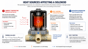
"Temperature Impacts on Solenoids – Part 2", https://magnet-schultzamerica.com/resources/blog/temperature-impacts-on-solenoids-part-2/. Thermal analyses of solenoid actuators show that electrical and magnetic losses produce heat in the coil and magnetic circuit, and that improved electromagnetic efficiency can reduce temperature rise under comparable operating conditions. Evidence role: mechanism; source type: paper. Supports: A source should explain solenoid losses, coil heating, and how actuator efficiency or duty cycle affects temperature rise.. Scope note: The degree of cooling benefit depends on coil resistance, drive method, ambient temperature, heat sinking, and duty cycle. ↩
"Solenoid stroke vs force - Electrical Engineering Stack Exchange", https://electronics.stackexchange.com/questions/438784/solenoid-stroke-vs-force. Engineering references define a solenoid force-stroke curve as the actuator force plotted against plunger displacement, supporting its use for evaluating available force throughout the stroke. Evidence role: definition; source type: education. Supports: A source should define force-stroke curves for solenoids or electromagnetic actuators and explain that force varies with plunger position.. ↩